


Effective December, 1998
IL 33-DAH-1
Page 4
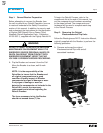
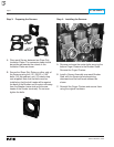
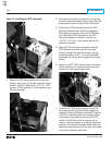
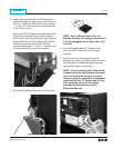
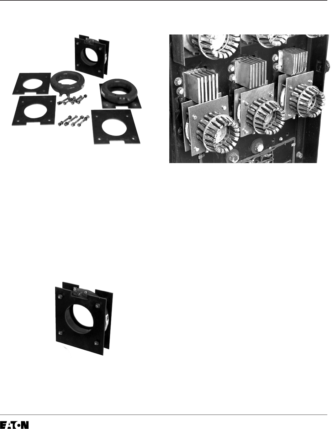
Step 3: Preparing the Sensors
A. Place each Sensor between two Glass Poly
Insulation Plates. The connector stabs should
be positioned towards the cutouts in the
Insulation Plates as shown.
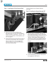
B. Secure the Glass Poly Plates on either side of
the Sensors using the (12) .250-20 × 2.00"
bolts, (24) flat washers, and (12) elastic stop
nuts supplied. Note that the bolts must be
installed so that the bolt heads will be against
the back of the Breaker and the stop nuts away
from the Breaker (same side as the screw
heads of the Sensor terminals). Do not over
tighten the bolts.
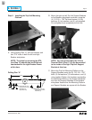
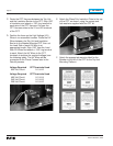
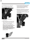
Step 4: Installing the Sensors
A. Remove and save the center bolts securing the
bottom Finger Clusters to the Breaker Stabs.
Remove the Finger Clusters.
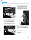
B. Install a Sensor Assembly over each Breaker
Stab, with the Sensor terminals pointing
downward and the bolt heads outward as
shown.
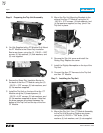
C. Reinstall the Finger Clusters and secure them
using the original hardware.