


Effective December, 1998
IL 33-DAH-1
Page 15
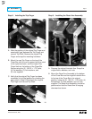
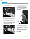
Step 15: Testing the Breaker
A. Measure the force necessary to trip the
Breaker at the point where the DTA impacts the
Trip Finger. The force necessary to trip the
Breaker MUST NOT EXCEED SEVEN (7) lbs.
B. The Retrofit must be tested using primary
injection. Refer to Section 8 of the
Instructions
for the Application of Digitrip RMS Retrofit Kits
on Power Circuit Breakers
(Publication
AD 33-855-1, June, 1997), supplied with the
Retrofit Kit, for detailed testing procedures and
specifications. For test information specific to
the Trip Unit, refer to the IL publication supplied
with the Retrofit Kit (see the Pick List for the
IL number).
C. While Section 8 of the
Instructions for the
Application of Digitrip RMS Retrofit Kits on
Power Circuit Breakers
provides the information
necessary for testing the Breaker, please keep
the following notes in mind when reviewing
other sections of the publication.
CAUTION:
When all testing is complete, the Trip
Unit must be reset. Failure to do so may cause
the battery in the Rating plug to run down.
Notes:
1. Publication AD-33-855 was created
specifically for the “hundred” series (500,
600, 700, etc.) Retrofit Kits. Therefore certain
sections and figures do not apply to the
“ten” series (510, 610, 810, etc.) Retrofit Kits.
Specifically, these are Sections 13 and 14, as
well as Figures 3-2, 3-3, and 3-4.
2.
For All Kits Other Than 510 Basic.
If testing
the Breaker with Short Delay or Ground
Fault functions, be sure to either plug in the
Cell Harness Assembly or use the Zone
Interlock Shorting Plug. Failure to do so may
result in shorter than expected trip times.
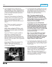
3.
For 810 and 910 Kits Only.
Without any
power applied to the system (neither the 120
volt power supply nor the Aux. Power
Module connected), plug the External
Harness into the Cell Harness and check the
impedance between COM 1 and COM 2. The
impedance should be between one (1) and
three (3) ohms. If the impedance is not
within this range, trace the wiring and
examine each connection to assure its
integrity.
Confirm that the IMPACC communication
wiring is correct by following the procedures
detailed in Section 7.4 of the Instructions for
the Application of Digitrip RMS Retrofit Kits
on Power Circuit Breakers. Note that for 810
and 910 Kits, the impedance between COM 1
and COM 2 should be between one (1) and
three (3) ohms.
When testing is complete, disconnect the
External Harness from the Cell Harness.
Final External Harness connection will be
performed in Step 16.
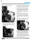
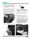
For Kits Supplied with a Cell Harness Only.
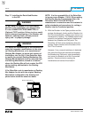
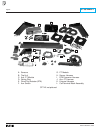
Step 16: Mounting the Cell Harness
A. The Cell Harness is to be mounted in the
Breaker Cell. The connector end is to be
mounted on the right front side of the Cell, in a
location suitable for connection with the
External Harness. The Terminal Blocks can be
mounted anywhere space is available in the
Cell as long as connection to the External
Harness can be made.
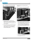
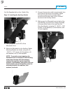
B. Route the Cell Harness wiring to keep it away
from any moving parts within the Cell Housing.