


Effective December, 1998
IL 33-DAH-1
Page 14
For Kits Supplied with an Aux. Switch Only.
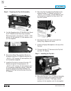
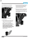
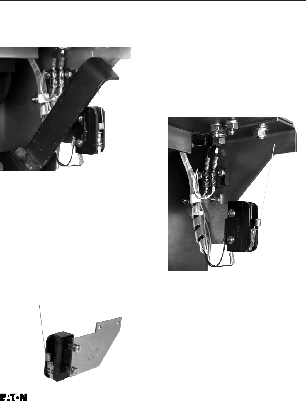
Step 14: Installing the Auxiliary Switch
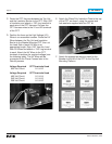
A. Using diagonals, cut 2.625" off the
Microswitch Arm.
B. Mount the Microswitch to the Auxiliary Switch
Mounting Bracket, as shown, using the (2)
.138-32 × 1.25" screws, (8) flat washers, (4)
lock washers, and (4) nuts supplied.
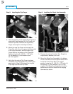
NOTE: To provide correct spacing, the
hardware must be installed in the following
order. Insert screws with flat washers
installed through the switch. Install flat
washers, lock washers, and tighten the nuts.
Install another set of flat washers, then the
mounting bracket, flat washers, lock
washers, and nuts.
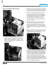
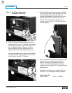
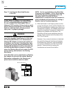
C. Connect the two wires (with ring terminals) from
the External Harness to the Auxiliary Switch.
Connect one wire to the normally “Open”
terminal and the other wire to the “Common”
terminal of the Auxiliary Switch.
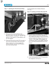
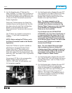
D. Making sure the Microswitch arm is behind the
Interlock Bar, mount the Aux. Switch Assembly
to the pre-drilled holes in the right Trip Unit
Mounting Bracket, using the (2) .164-32 × .500"
screws, (4) flat washers, (2) lock washers, and
(2) nuts supplied.