


Effective December, 1998
IL 33-DAH-1
Page 11
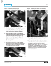
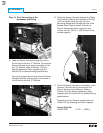
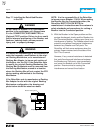
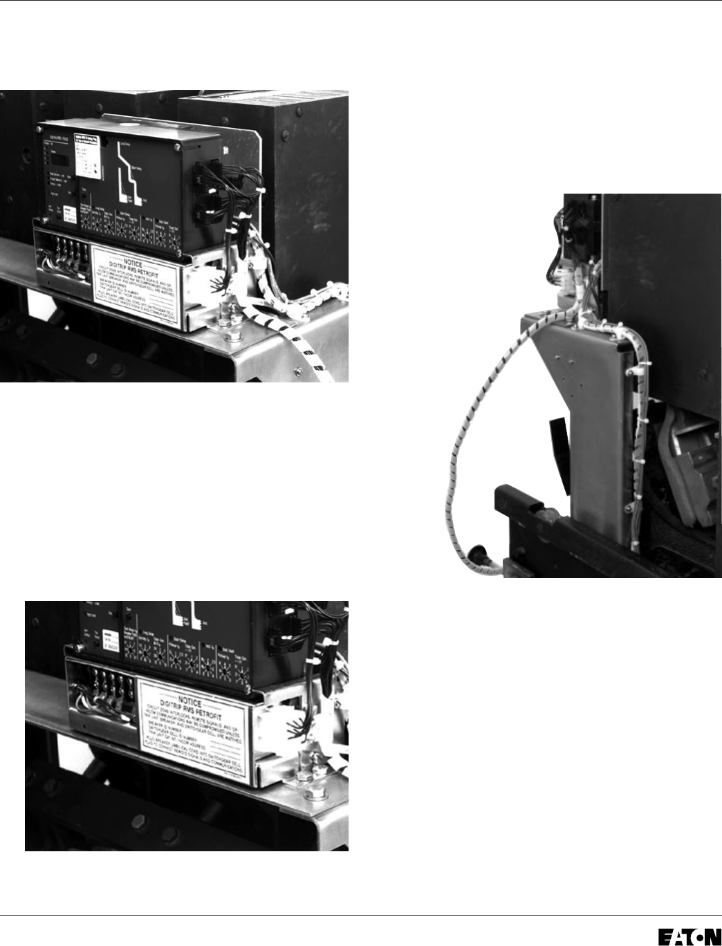
Step 13: Final Connection of the
Harnesses and Wiring
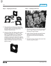
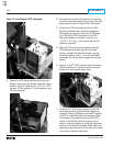
A. Feed the Sensor Harness through the hole in
the left side of the Aux. CT Module. Connect the
Sensor Harness to the proper terminals on the
Aux. CT Module. Refer to Section 12 of the
Retrofit Application Data, supplied with the
Retrofit Kit, for detailed wiring specifications.
Connect the green ground wire from the Sensor
Harness (with the ring terminal) to the screw in
the left side of the Aux. CT Module.
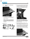
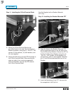
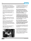
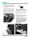
B. Route the Sensor Harness between the Glass
Poly Insulation Barrier and the back of the Trip
Unit, then down along the right Trip Unit
Mounting Bracket and through the hole in the
Breaker Back Plate as shown. Secure the
Sensor Harness as shown using the wire
clamps and (6) .138-20 × .500" thread cutting
screws supplied.
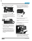
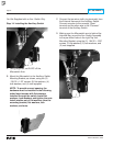
C. Route the Sensor Harness to the bottom of the
Sensors. Connect the ring terminals of the
Sensor Harness to the Sensors. Refer to
Section 12 of the Retrofit Application Data,
supplied with the Retrofit Kit, for detailed wiring
specifications.
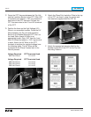
Depending on the Sensors supplied with the
Retrofit Kit, the following convention applies.
Sensor Style No.
4A35613H01 X1-X2 = 3000 A