


Effective December, 1998
IL 33-DAH-1
Page 8
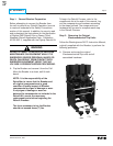
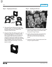
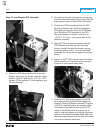
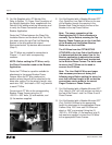
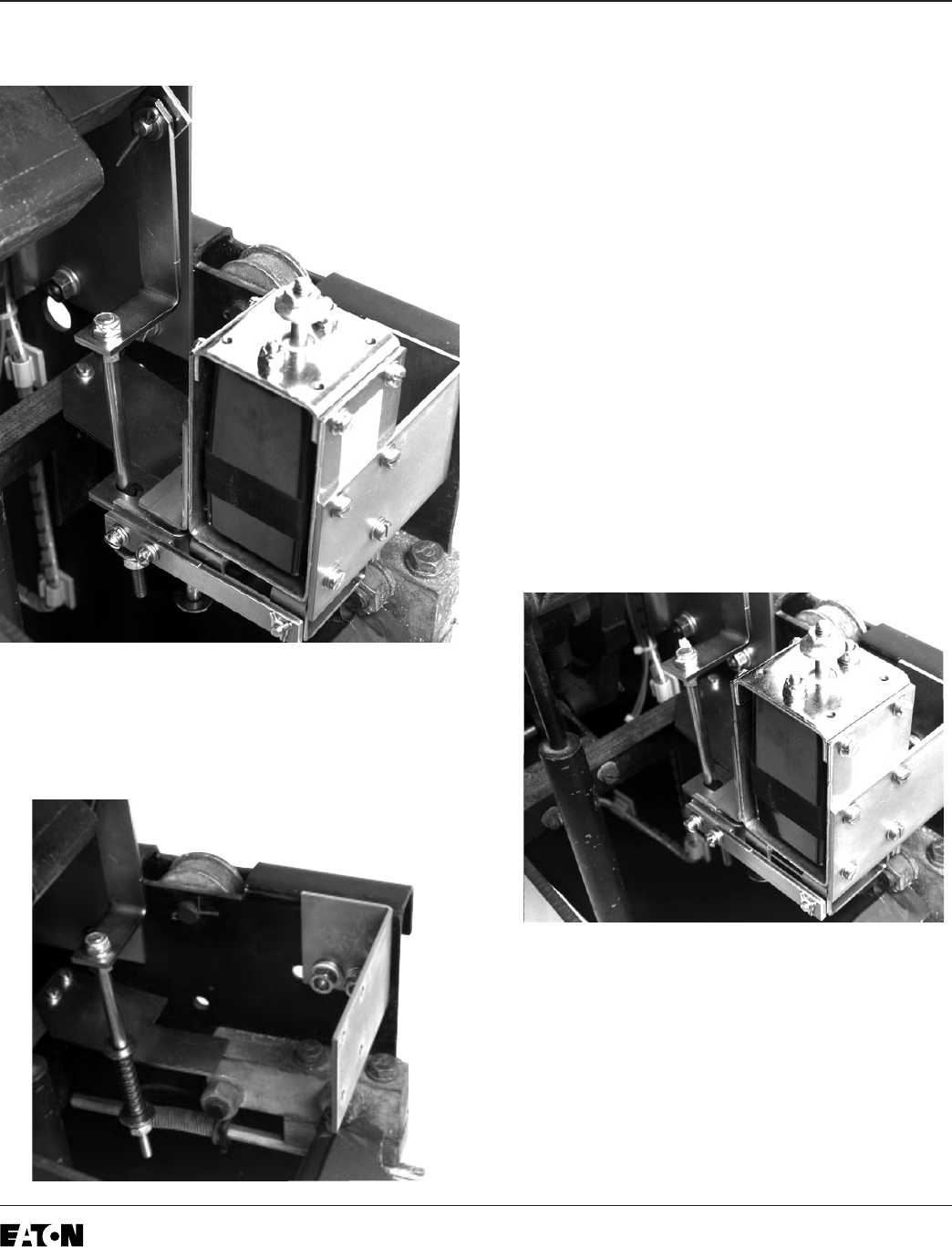
Step 10: Installing the DTA Assembly
A. Mount the DTA Mounting Bracket to the right
Breaker side panel, as shown, using the holes
drilled in Step 5 A and the (2) .312-18 × .750"
screws, (2) flat washers, (2) lock washers, and
(2) nuts provided.
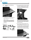
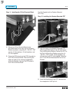
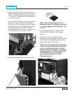
B. Remove the two nuts, flat washers, and spring
from the Reset Assembly, being careful that the
brass spacer does not slide off the all-thread.
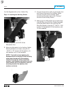
C. Position the DTA Assembly behind the DTA
Mounting Bracket, with the Reset Assembly
Shaft going through the slot in the DTA Reset
Arm. Mount the DTA Assembly to the DTA
Mounting Bracket, as shown, using the (4)
.164-32 × .312" pan / lock screws and (4) flat
washers provided.
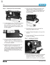
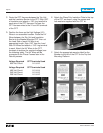
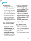
D. With the DTA in the latched position and the
DTA Release Arm lifted up over the brass
sleeve, reinstall the large flat washer, spring,
small flat washer, and (1) nut onto the Reset
Assembly Arm. Snug the nut against the brass
sleeve.
E. Apply Loc-Tite
®
242 to the threads at the base
of the installed nut. Install the second nut and
tighten the nuts against each other.
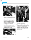
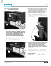
F. Connect a 24 VDC power supply to the DTA
terminals; positive to positive and negative to
negative. Close the Breaker manually. Energize
the DTA to trip the Breaker; de-energize when
the Breaker trips. Make certain that the DTA
resets. If the Breaker fails to properly trip or
reset, it may be necessary to shorten the brass
spacer on the Reset Assembly Shaft. Make the
necessary adjustments until the trips and resets
are sure and positive each time.