


Effective December, 1998
IL 33-DAH-1
Page 5
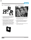
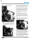
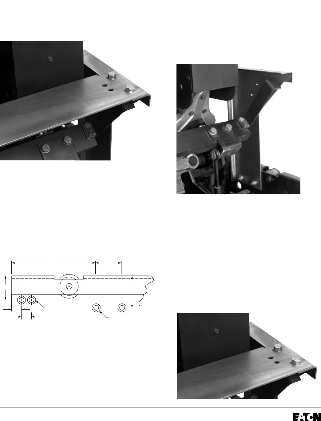
Step 5: Installing the Trip Unit Mounting
Platform
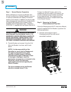
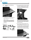
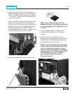
A. Using Drilling Plan “A”, drill and counter sink
two .375" holes in both the left and right
Breaker side plates.
NOTE: The holes for mounting the DTA
(see Step 10) should also be drilled and
countersunk in the right Breaker Frame
at this time.
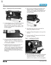
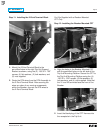
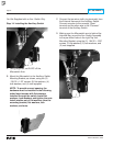
B.
Mount the right and left Trip Unit Support Brackets
to the Breaker side plates as shown, using the
(4) .312-18 × .750" flat head screws, (4) flat
washers, (4) lock washers, and (4) nuts
supplied.
Do not tighten them completely at this time.
NOTE: For ease of assembly, the 2-Point
Terminal Block (Step 11-A) can be mounted
to the inside of the right Trip Unit Support
Bracket at this time.
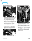
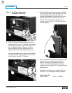
C. Mount the Trip Unit Mounting Platform to the
Support Brackets using the (4) .312-18 × .750"
bolts, (8) flat washers, (4) lock washers, and (4)
nuts supplied. Tighten the hardware connecting
the Mounting Platform to the Support Brackets,
and then the Support Brackets to the Breaker
side plates. Assure that the Mounting Platform
and Support Brackets are square with the Breaker.
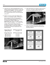
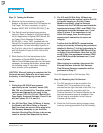
0.75"
1.81"
6.50" 2.00"
2.38"
0.75"
Drill 0.375" Dia. and
Countersink to 0.578"
Head Size (2)
Right Side Only
Drill 0.375" Dia. and
Countersink to 0.578"
Head Size
(
4
)
Drilling Plan “A”