


Effective December, 1998
IL 33-DAH-1
Page 7
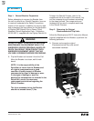
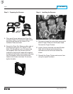
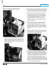
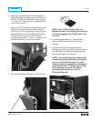
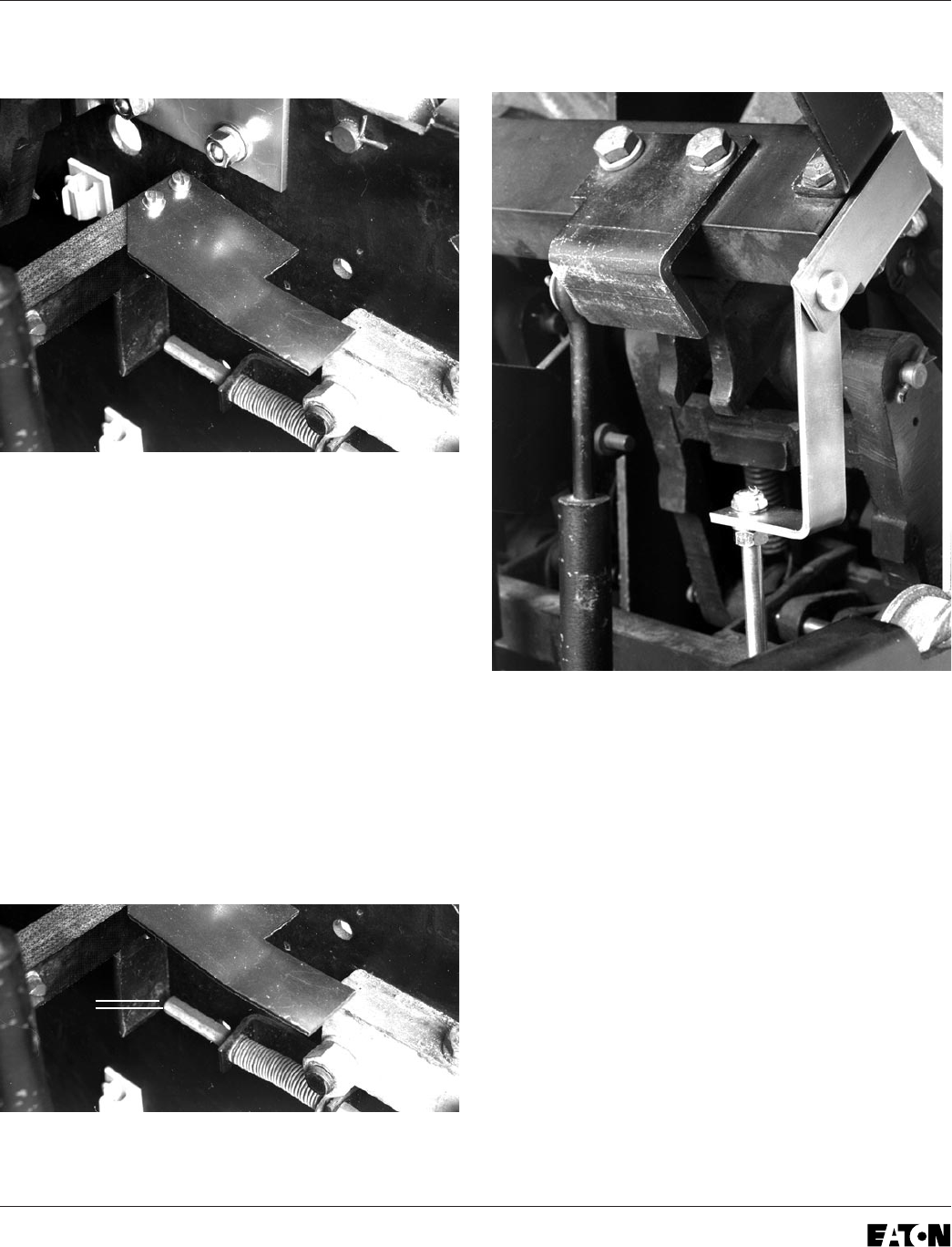
Step 8: Installing the Trip Finger
A. Note the position of the original Trip Finger and
associated “gap” between the Trip Finger and
manual Trip Shaft. Remove the original Trip
Finger and scrap the mounting hardware.
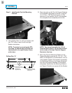
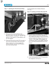
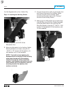
B. Mount the new Trip Finger on the top of the
Cross Bar (with the curve upward and the notch
to the right) as shown, and the original Trip
Finger back on the bottom of the Cross Bar.
Secure using the (2) .190-32 × 1.75" bolts,
(4) flat washers, (2) lock washers, and
(2) nuts supplied.
C. Verify that the original Trip Finger has been
reinstalled in its initial position by checking the
gap (noted in Step 8-A) between the original
Trip Finger and manual Trip Shaft.
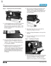
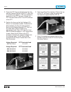
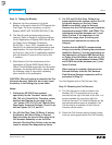
Step 9: Installing the Reset Arm Assembly
A. Remove the original Interlock Arm. Scrap the
original bolts, washers, and nuts.
B. Mount the Reset Arm Assembly to the bottom
of the Cross Bar and the original Interlock Arm
to the top of the Cross Bar in its original
position, using the (2) .190-32 × 1.75" bolts, (4)
flat washers, (2) lock washers, and (2) nuts
supplied. The Reset Arm Assembly should be
positioned so that the Reset Arm is hanging
downward as shown.
GAP