


Current Loop Compensation (Series 668xA Only) 129
E
Current Loop Compensation (Series 668xA Only)
Introduction
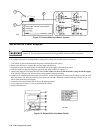
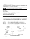
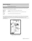
This section describes how you may use current loop compensation to optimize for inductive loads or for fast CV/CC mode
crossover. A 7-position compensation switch for this purpose is located under the cover on the rear of the power supply.
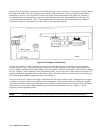
Function of Loop Compensation
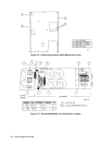
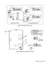
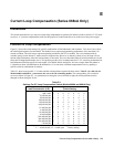
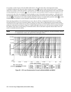
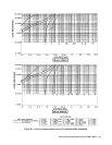
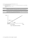
Figure E-1 shows the switch settings for specific combinations of load inductance and resistance. Two sets of curves show
the small-signal response for each model. The dashed curves represent programming performance of no more than 10%
current overshoot. The solid curves represent operating conditions with 25% overshoot. The curve obtained with all
switches open gives the fastest CC mode crossover response time. However, as shown by these curves, the loop will not
tolerate larger inductances unless the load resistance is increased. The curve described when all switch positions are closed
shows the as-shipped performance curve. This position provides 10% overshoot and fast CV/CC crossover performance for
load inductances that are specific for each model. (For Models 6680A and 6681A, this curve ranges from 100
µohms at
15
µhenries to about 100 milliohms at 40 millihenries.). You can select a different compensation curve by opening a
specific switch or combination of switches.
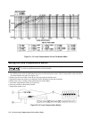
Table E-1 shows some specific L
÷ R ratios and the switch positions required for these ratios. Table E-1 is valid only for
Models 6680A and 6681A - you must use the curves for the remaining models.
The corresponding 10% overshoot
curves are shown in Figure E-1. As operation moves along the curves from left to right, the switch positions must be
changed as shown along the X-axis.
Table E-1.
Settings For CC Loop Compensation Switch (Models 6680A and 6681A Only)
Load Characteristic (L/R)
1
Switch Setting
7 6 5 4 3 2 1
1 µH/3 mΩ
0 0 0 0 0 0 0
2
15 µH/100 µΩ
1 1 1 1 1 1 1
30 µH/100 µΩ
0 0 0 0 0 0 1
100 µH/100 µΩ
1 1 1 1 1 1 0
150 µH/100 µΩ
0 0 0 0 0 1 0
600 µH/100 µΩ
1 1 1 1 1 0 0
1.2 mH/100 µΩ
0 0 0 0 1 0 0
4 mH/100 µΩ
1 1 1 1 0 0 0
10 mH/100 µΩ
0 0 0 1 0 0 0
40 mH/100µΩ
1 1 1 0 0 0 0
100 mH/100 µΩ
0 0 1 0 0 0 0
380 mH/100 µΩ
1 1 0 0 0 0 0
650 mH/100 µΩ
0 1 0 0 0 0 0
7 H/100 µΩ
1 0 0 0 0 0 0
1
"1" = switch closed; "0" = switch open.
2
Factory setting.