Calibration 95
A
Calibration
Introduction
The power supply may be calibrated either from the front panel or from a controller over the GPIB. The procedures given
here apply to all models.
Important These instructions do not include verification procedures. If you need to perform verification as a
erequisite to or as part of your calibration procedure, see “Appendix B - Verification”.
Equipment Required
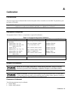
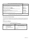
The equipment listed in Table A-1, or equivalent, is required for calibration.
Table A-1. Equipment Required for Calibration
Equipment Characteristics Recommended Model
Voltmeter D-c accuracy 0.005%, 6 digits Agilent 3456A or 3458A
Shunt resistor
Agilent 6641A, 51A, 52A
100 A, 0.01 Ω, 0.04%, 100 W
Guildline 9230/100
Agilent 6642A, 43A, 44A, 45A,
6643A, 54A, 55A
15 A, 0.1 Ω, 0.04%, 25 W
Guildline 9230/15
Agilent 6671A
300 A, 0.001 Ω, 0.04%,100 W
Guildline 9230/300
Agilent 6672A, 73A, 74A, 75A
300 A, 0.001 Ω, 0.04%, 100 W
Guildline 9230/300
Agilent 6680A, 81A, 6690A
1000 A, 0.1 mΩ, 0.05%
Burster 1280S
Agilent 6682A, 83A, 84A,
6691A, 92A
300 A, 0.001 Ω, 0.04%,100 W
Guildline 9230/300
For Calibration Over the GPIB
GPIB Controller
IBM compatible PC with GPIB Interface
General Procedure
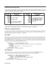
Because the power supply output must be enabled during calibration, voltages or currents
hazardous to personnel and/or damaging to equipment can appear at the output terminals.
ENERGY HAZARD. Series 668xA/669xA supplies can provide more than 240 VA at more than 2
V. If the output connections touch, severe arcing may occur resulting in burns, ignition or welding of
parts. Do not attempt to make connections to live output circuits.
Parameters Calibrated
The following parameters may be calibrated:
• Output voltage.
• Output voltage readback.


