


User Connections 72
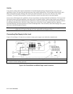
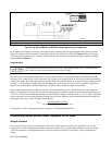
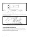
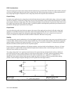
Load Leads Remote Sense Points
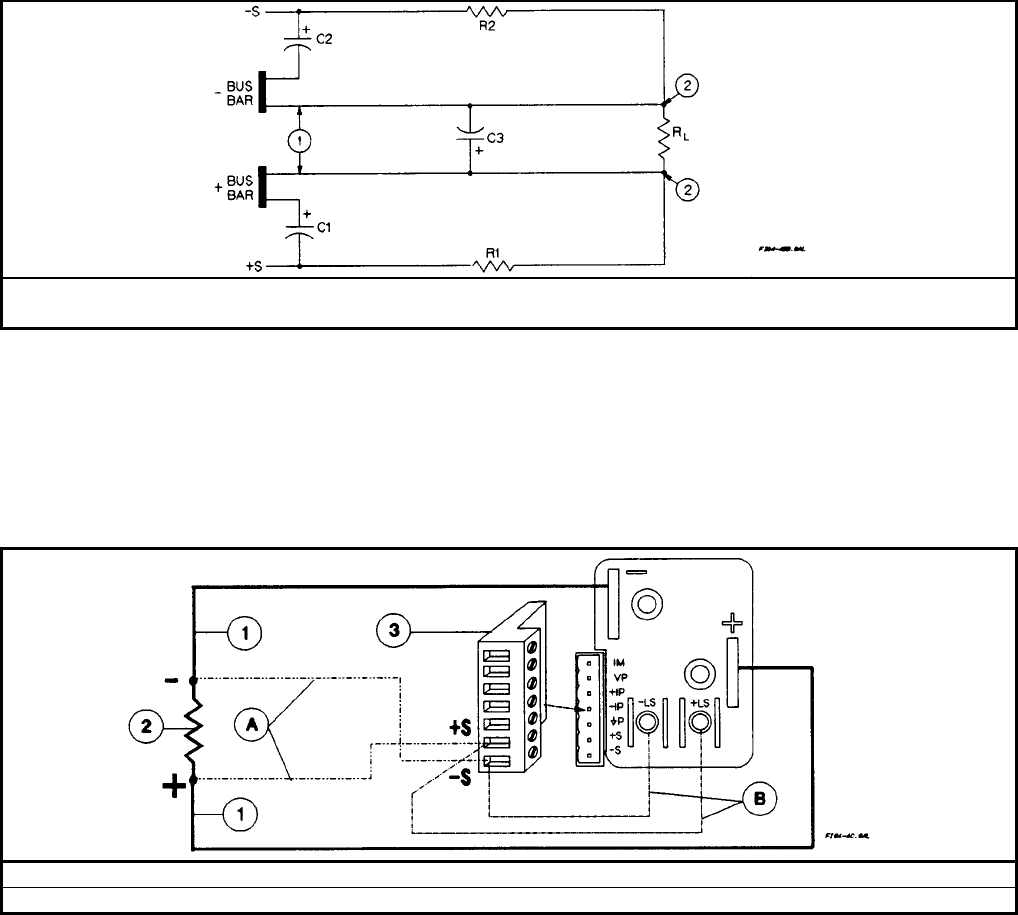
Cl, C2 = 33 µF
C3 = Load bypass capacitor
R1, R2 = 20 Ω, 1%
Figure 4-4b. Series 667xA Sense Lead Bypass Network
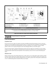
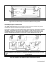
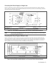
Connecting One Power Supply to a Single Load
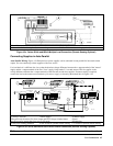
Figure 4-4c shows how to connect a single power supply to one load. Keep output load leads close together (small loop
area) to obtain a low inductance and low impedance connection to the load. If you wish to use remote sensing, connect the
sense leads at the load as shown in the figures.
Load Connection Load Analog Connector
A Connect for remote sensing (optional) B Connect for local sensing (default)
Figure 4-4c. Series 667xA Single Load Connection (Remote Sensing Optional)
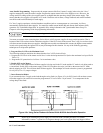
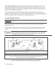
Connecting One Power Supply To Multiple Loads
Figure 4-4d shows how to connect a single power supply to more than one load. When connecting multiple loads to the
power supply with local sensing, connect each load to the output bus bars with separate connecting wires. This minimizes
mutual coupling effects and takes full advantage of the supply's low output impedance. Keep each pair of load wires as short
as possible and twist or bundle them to reduce lead inductance and noise pickup.