


Installation 43
2
Installation
Inspection
Damage
When you receive your power supply, inspect it for any obvious damage that may have occurred during shipment. If there is
damage, notify the shipping carrier and the nearest Agilent Sales and Support Office immediately. Warranty information is
printed in the front of this guide.
Packaging Material
Until you have checked out the power supply save the shipping carton and packing materials in case the power supply has to
be returned to Agilent Technologies. If you return the power supply for service, attach a tag identifying the model number
and the owner. Also include a brief description of the problem.
Items Supplied
In addition to this manual, check that the following items in Table 2-1 are included with your power supply (see Table 1-6
for part numbers):
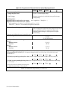
Table 2-1. Items Supplied
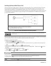
Power cord Series 664xA and 665xA
Your power supply was shipped with a power cord for the type of outlet specified for your location. If
the appropriate cord was not included, contact your nearest Agilent Sales and Support Offices (see end
of this guide) to obtain the correct cord. Caution: Your power supply cannot use a standard power cord.
The power cords supplied by Agilent Technologies have heavier gauge wire.
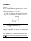
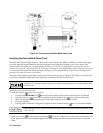
Series 667xA, 668xA, 669xA
Your power supply was shipped with a power cord appropriate for your location. The cord may or may
not be terminated in a power plug (see "Options" in Chapter 1). If the cord is not included, contact your
nearest Agilent Sales and Support Office (see end of this guide ) to obtain the correct cord. These
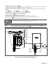
models also include a power input safety cover with strain relief connector. It is required to secure the
power cord to the power supply.
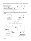
Analog
connector
A 7-terminal analog plug (see Table 1-6) that connects to the back of the supply. Analog connections are
described in Chapter 4.
Digital
connector
A 4-terminal digital plug (see Table 1-6) that connects to the back of the supply. Digital connections are
described in "Appendix D - Digital Port Functions"
Serial cable
A 2-meter cable (see “Accessories” in Chapter 1) that connects to the control bus (next to the GPIB
connector). This cable is used to serially connect multiple supplies as described under "Controller
Connections" in Chapter 4.