


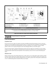
User Connections 65
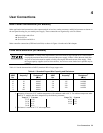
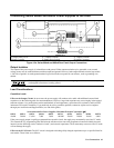
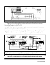
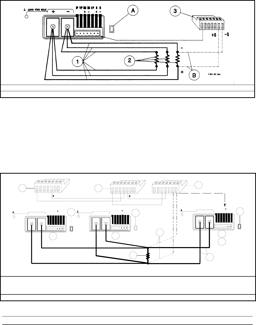
c Load Connection d Loads e Analog Connector
A Set switch for local or (optional) remote sensing B Connect for remote sensing (optional)
Figure 4-3c. Series 664xA and 665xA Multiple Load Connection (Remote Sensing Optional)
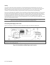
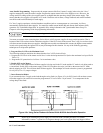
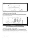
Connecting Supplies in Auto-Parallel
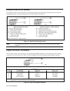
Auto-Parallel Wiring. Figure 4-3d illustrates how power supplies can be connected in auto-parallel for increased current
output. You can connect up to three supplies of the same model .
Use load leads of a sufficient wire size so that the absolute voltage difference between the + output terminal of the "master"
supply and the + output terminal of the first "slave" supply is kept under 2 V at rated current. This also applies to the
voltage difference between the + output terminals of the first and second slave supplies. If remote sensing is required,
connect the load to the remote sense terminals of the master supply, as shown by the dashed lines in Figure 4-3d.
+-
+
IM
-
IMIP
+
S
-
SVP IP
1
FIG4-3D.GAL
+-
+
IM
-
IM
IP
+
S
-
SVP I P
+-
+
IM
-
IMIP
+
S
-
S
+240 VDC MAX_
VP I P
+
-
+S -S
-IM
+IM
IP
+IM
-IM
IP
1
1
2
A
5
2
A
B
3
4
6
C
IP
IP
+240 VDC MAX_
+240 VDC MAX_
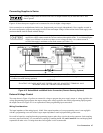
cAnalog Connector dSlave Supply e Master Supply
fProgram only the master. Set slave output and OVP voltages slightly higher
than the master to ensure that slaves stay in CC mode.
gLoad
hConnection
A Only local sensing permitted B Set switch for optional remote sensing C Connect for optional remote sensing
Figure 4-3d. Series 664xA and 665xA Auto-Parallel Connection (Remote Sensing Optional)
Note To avoid output oscillations, observe the wiring suggestions given under “External Voltage Control”.