


Installation 49
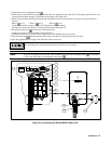
3. Tighten the screws securing the clamp .
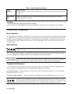
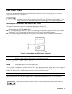
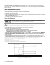
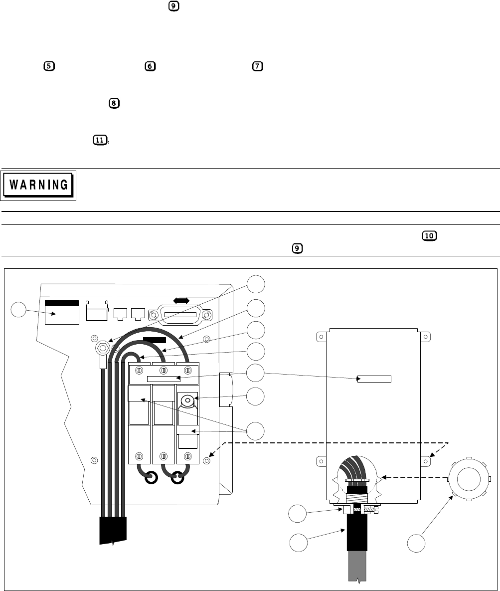
4. Insert the line cord with the cable clamp into one of the two openings on the safety cover. (The figure shows the line cord
installed in the bottom opening.) Tighten the cable clamp to the safety cover.
5. Remove the insulation from the pre-striped end of the three ac lines. Secure the lines in the top of each fuse holder as
follows:
Phase 1 to L1. Phase 2
to L2. Phase 3 to L3.
Torque the conductive clamp screws to 35 inch-pounds (4 newton meters).
Pull up on the wire to check that it is securely fastened and cannot pull out.
6. Secure the ground wire to the chassis earth ground stud.
Torque the stud nut to 35 inch-pounds (4 newton meters).
7. Position the safety cover over the fuses and secure the cover with the four cover screws.
8. Place the metal cap into the opening of the safety cover that is not being used by the line cord.
9. Wire the appropriate power plug to the other end of the power cord.
Do not apply power to the instrument unless the safety cover is in place.
Note If you are providing your own power cable, remember to position the insulating sheath over the end
of the wires where they pass through the cable clamp .
L1 L2 L3
WARNING:
For continued protection against
fire hazard replace fuse with the
same type and rating.
10
1
INTERNAL FUSES
3
FUSES
UNDER
COVER
FUSES BLOWN
WHEN RED FLAG
IS IN WINDOW
LINE RATING
DIG CNTL
J1 J2
9
5
6
7
8
2
4
11
Figure 2-6. Connecting the Series 669xA Power Cord