


136 Output Bus Bar Options
Option 602 Installation
WARNING ENERGY HAZARD. The Series 668xA/669xA power supplies can provide more than 240 VA at
more than 2 V. If the output connections touch, severe arcing may occur resulting in burns,
ignition or welding of parts. Do not attempt to make connections while the output is live.
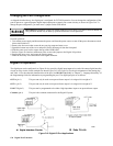
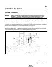
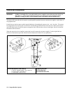
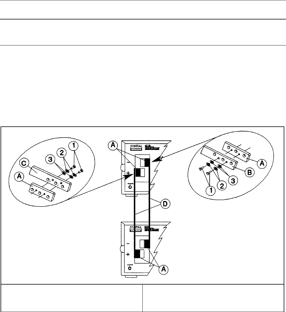
The Option 602 kit provides bus bar spacers to permit parallel operation between vertical power supplies, such as those in
an equipment rack.
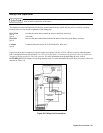
Each kit has two bus bar spacers and the required hardware for attaching the spacers to the
− and + bus bars. The spacers
have tapped holes for receiving the screws that are inserted through clearence holes in the bus bars. Either spacer may be
used with either bus bar. Secure the spacers on opposite sides of the bus bars as shown in the figure. Be sure to insert the
flatwashers and lockwashers.
When the spacers have been installed, connect the bus rails between the two power supplies. Use the original bus bar
hardware or the hardware provided with the Bus Bar Hardware Kit 5080-2313 (see option 601)
(A) Bus Bar Spacer, 5040-1699 (2)
(1) Screw, machine M4x0.7, 0515-0981 (4)
(2) Lockwasher, 2190-0484 (4)
(3) Flatwasher, 3050-1053 (4)
(B) Minus Bus Bar
(C) Plus Bus Bar
(D) Customer bus rails