


Ouptut Bus Bar Options 135
G
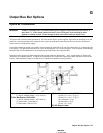
Output Bus Bar Options
Option 601 Installation
WARNING ENERGY HAZARD. The Series 668xA/669xA power supplies can provide more than 240 VA at
more than 2 V. If the output connections touch, severe arcing may occur resulting in burns,
ignition or welding of parts. Do not attempt to make connections while the output is live.
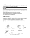
The Option 602 kit allows bench operation of the Series 668xA/669xA power supplies. It provides an insulating cover and
means for vertical conections to the output bus bars to prevent accidental contact between the two bus bars and external
objects at the rear of the power supply.
Each option contains an output cover with a cutout to permit the load leads to be run down from above or up from below the
power supply. The option also includes four screws for fastening the cover to the rear panel, a bus bar spacer with mounting
hardware, and a bus bar hardware kit for connectiong the load leads to the output bus bars.
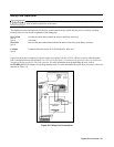
Install the bus bar spacers on either output bus bar to permit clearence between the
− and + output leads (see Option 602
instructions for mounting details). Using the bus bar hardware kit, connect the output leads either from above or below the
bus bars. Then install the output cover and secure it with the four machine screws provided.)
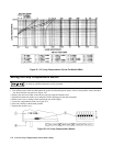
(A) Output Cover, 5040-1692
(1) Screw, machine M4x0.7, 0515-1085 (4)
(C) Bus Bar Spacer, 5040-1699
(1) Screw, machine M4x0.7, 0515-0981 (4)
(2) Lockwasher, 2190-0484 (4)
(3) Flatwasher, 3050-1053 (4)
(B) Bus Bar Hardware Kit, 5080-2313
(1) Bolt, 3/8 x 16 x 1.25 lg (3)
(2) Bolt, 3/8 x 16 x 1.75 lg (3)
(3) Lockwasher, 3/8 (6)
(4) Flatwasher, 3/8 (6)
(5) Nut, 3/8 x 16 (6)
(D) DC Output Leads
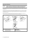
1. Relay Board
2 Cut W603 W604
1. Relay Board
2 Cut W603 W604