


Front Panel Operation 86
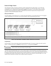
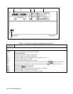
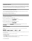
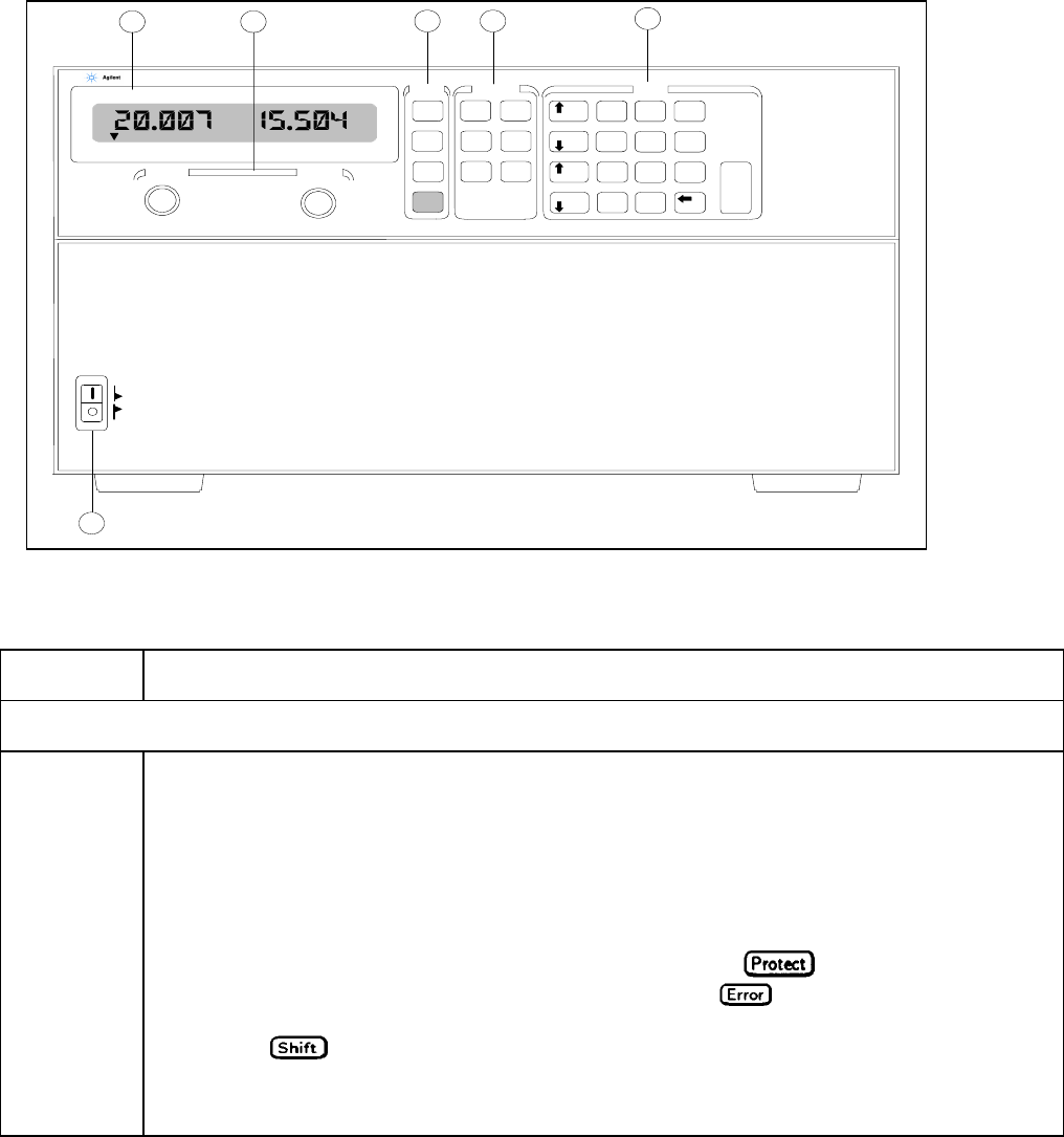
Figure 5-1. Front Panel Controls and Indicators
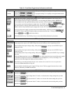
Table 5-1. Front Panel Controls and Indicators (see Figure 5-1)
Control or
Indicator
Function or Indication
Display
VOLTS
Shows present output voltage of the power supply.
AMPS
Shows present output current of the power supply.
Status Annunciators
CV
The power supply is in constant-voltage mode.
CC
The power supply is in constant-current mode.
Unr
The power supply output is unregulated (output is neither CV or CC).
Dis
The power supply output is disabled.
OCP
The overcurrent protection function is enabled.
Prot
A protection circuit has caused the power supply to shut down. (Press to determine the reason.)
Err
An error has been generated as a result of remote operation. (Press to display the error code).
Cal
The power supply is in calibration mode.
Shift
The shift key has been pressed.
Rmt
The power supply is in the remote mode (controlled over the GPIB).
Addr
The power supply is addressed to listen or talk.
SRQ
The power supply is requesting service from the controller.
VOLTS
AMPS
6681A
0-8V/0-580A
CV CC Unr Dis OCP Prot Err Cal Shift Rmt Addr SRQ
Off
On
Local
Error
Save
Recall
Addres s
Output
on/off
Protect
OV
Voltage
OCP
Current
VCal
Cal Save
Enter
-
3
21
0
.
789
4
56
Voltage
Voltage
Current
Current
ICal
Pass
Cal Enable Cal Disable
Prot Clear
31
5
4
SYSTEM DC POWER SUPPLY
OVCal
Clear Entry
SYSTEM
FUNCTION
ENTRY
2
VOLTAGE CURRENT
6