Calibration 99
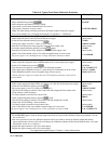
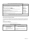
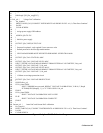
Table A-2. Typical Front Panel Calibration Procedure (continued)
Action
Display Response
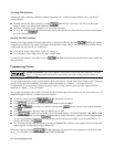
Calibrating Current Monitor (I
M
) (Series 668xA/669xA Only)
If you perform this calibration, then you must recalibrate the current output.
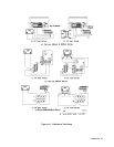
1. Make certain the appropriate shunt resistor (see Table A-1) is the only load on the power
supply.
2. Select IMN calibration by pressing
If the power supply is not in CC mode, an error occurs.
4
3. Wait for DVM reading to stabilize. Then read DVM and compute the current value
(DVM reading
÷ shunt resistance).
4. Use Entry keypad to enter the current value.
Note: If the entered value is not within acceptable range, an error occurs.
Wait for the power supply to compute the new current calibration constants, which will be
stored in RAM.
If the constant is not within acceptable range, an error occurs.
(Meter mode)
IMON CAL
WRONG MODE
(Meter mode)
(Meter mode)
CAL ERROR
CAL COMPLETE
CAL ERROR
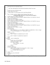
4.
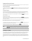
Program the output voltage to 10% of its rated output*
*See applicable Output Ratings in “Chapter 1- General Information”
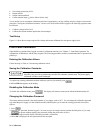
Recovering From Calibration Problems
You can encounter serious calibration problems if you cannot determine a calibration password that has been changed or the
power supply is severely out of calibration. There are jumpers inside the power supply that permit the calibration password
to be defeated and allow the original factory calibration constants to be restored. These jumpers are explained in the
Service
Manual.
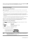
Calibration Error Messages
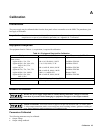
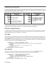
Error messages that can occur during calibration are shown in Table A-3.
Table A-3. GPIB Calibration Error Messages
Error
No.
Meaning
Error
No.
Meaning
1 CAL jumper prevents calibration
1
6 Wrong CAL command sequence
2 CAL password is incorrect 7 Incorrect state (CV/CC) for this command
3 CAL mode is not enabled
4 Incorrect computed readback constants
5 Incorrect computed programming
constants
1
This is a hardware disable. See the power supply
Service Manual.


