


User Connections 83
Controller Connections
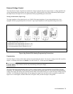
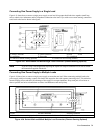
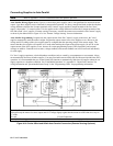
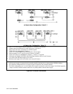
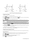
Figure 4-6 shows two basic ways of connecting your power supply to a controller. They are "linked" and "stand-alone
configurations.
Stand-Alone Connections
See Figure 4-6A. Each stand-alone power supply has its own GPIB bus address. Stand-alone power supplies may be
connected to the bus in series configuration, star configuration, or a combination of the two. You may connect from
1 to 15 stand-alone power supplies to a controller GPIB interface.
Linked Connections
See Figure 4-6B. Up to 16 power supplies may be used at a single GPIB primary bus address by making linked
connections. (You cannot use linked connections if you intend to program power supplies with the Compatibility
Language - see the power supply “Programming Guide".)
■ The first power supply in a linked connection is a "direct supply" connected to the controller via a GPIB cable. The
direct supply is the only supply connected directly to the bus and has a unique primary bus address.
■ The remaining power supplies are "linked supplies” connected to the direct supply via a serial-link cable. Each
linked supply has a unique secondary GPIB address and derives its primary address from the direct supply. You may
connect from 1 to 15 linked supplies to each direct supply.
Note The power supply is shipped from the factory with its GPIB address set to 5. The power supply primary
and secondary addresses can be changed from the front panel as described in "Chapter 2 - Remote
Programming" of the "Programming Guide". For power supply GPIB interface capabilities, see Table
1-5 in Chapter 1 of this guide.