


User Connections 60
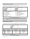
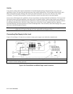
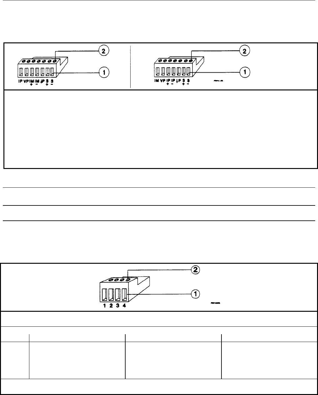
Analog Connector (All Models)
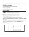
This connector, which is on the rear panel, is for connecting remote sense leads, external current monitors, and external
programming sources. The connector accepts wires sizes from AWG 22 to AWG 12.
Insert Wires
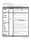
Agilent Series 664xA & 665xA
IP Current programming input.
VP Voltage programming input.
+IM Current monitor output.
--IM Current monitor output.
↓P Common for VP, IP and IM signals
1
.
+ S + remote sense input.
--S -remote sense input.
Tighten Screws
Agilent Series 667xA, 668xA, & 669xA
IM Current monitor output.
VP Voltage programming input.
+IP Differential current programming input.
--IP Differential current programming input.
↓P Common for VP and IM signals
1
.
+S + remote sense input.
--S -remote sense input.
NOTE
1
: Referenced to + output terminal.
Figure 4-1. Rear Panel Analog Connector
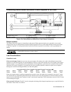
Note It is good engineering practice to twist and shield all signal wires to and from the analog and digital
connectors.
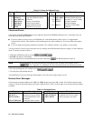
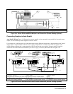
Digital Connector (All Models)
This connector, which is on the rear panel, is for connecting fault/inhibit, digital I/O, or relay link signals. The connector
accepts wires sizes from AWG 22 to AWG 12. Refer to Appendix D for more information about using this connector.
Insert Wires Tighten Screws
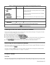
FUNCTION
1
Pin No. Fault/Inhibit Digital I/O Relay Link
2
1
2
3
4
FLT OUTPUT
FLT OUTPUT
INH INPUT
INH COMMON
OUT 0
OUT 1
IN/OUT 2
COMMON
RLY SEND
NOT USED
RLY RTN
COMMON
NOTES: Factory default function is FAULT/INHIBIT.
Output relay is not used with Series 668xA and 669xA.
Figure 4-2. Rear Panel Digital Connector