


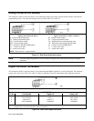
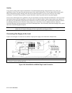
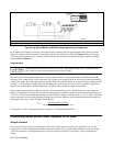

User Connections 68
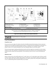
Analog connector
l=Voltage programming source 0 to --5 V 2=Current programming source 0 to --5 V
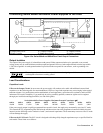
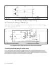
Figure 4-3g. Series 664xA and 665xA Analog Programming Connections
If you cannot avoid capacitive coupling, it may help to place capacitors from the unused programming inputs to ground.
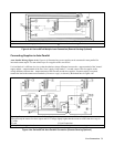
Especially with auto-parallel operation, connecting a capacitor (≥4,000 pF) from VP to P Common on the master supply
will ensure proper operation. Also with auto-parallel operation, do not allow more than about 500 pF capacitive loading
between IM and Common P.
Programming
Make certain that the common connection for your voltage programming source is isolated from the
load. Failure to do this may cause damage to the power supply.
The effect of the analog programming source is always summed with the values programmed over the GPIB or from the
front panel. The voltage source can act alone only if you set the other program sources to zero. Keep the total programmed
setting of the supply (the analog input summed with the GPIB or front panel settings) at or under the output ratings specified
in Table 1-1a. Exceeding the output ratings will not damage the supply, but it may not be able to regulate its output at the
higher levels. If this happens, the Unr annunciator will light to warn you that the output is unregulated.
When voltage programming the output, the frequency of the programming source is limited by the slew rate of the power
supply. To keep the power supply from slewing its output (going into nonlinear operation), the maximum programming rate
is 3750 V/s. The maximum downprogramming rate (when the power supply is sinking current) is 750 V/s. These restrictions
can be expressed as the maximum programming frequency that can be applied without causing distortion at the output. The
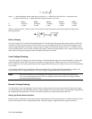
following formula can be used to determine this frequency:
F
MAX
= 50(voltage rating of supply)
p-p amplitude of desired output sine wave
At frequencies >6 kHz, voltage programming is subject to a 3 dB bandwidth limitation.
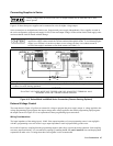
Connecting Series 667xA Power Supplies to the Load
Output Isolation
The output of the power supply is isolated from earth ground. Either output terminal may be grounded, or an external
voltage source may be connected between either output and ground. However, both output terminals must be kept within
± 240 Vdc of ground. An earth ground terminal is provided on the rear panel for convenience, such as grounding wire
shields.