


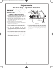
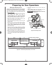
!.86;4.;BE696.?F2;02
Certain types of molding need a fence face extension
because of the size and position of the workpiece.
Holes are provided in the fence to attach an auxiliary
fence. The auxiliary fence is used with the saw in the
0° bevel position only
.
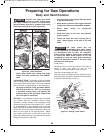
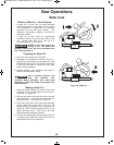
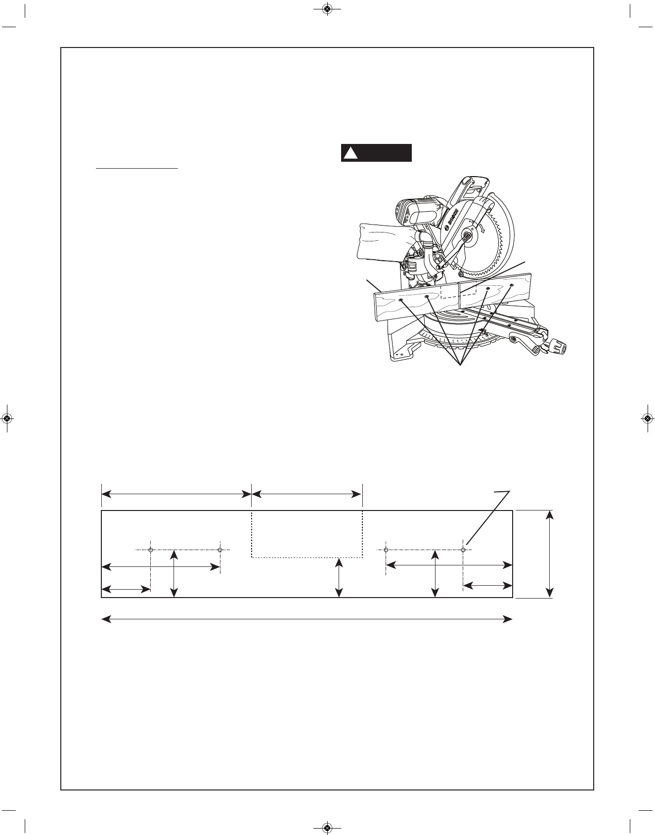
1. Place a piece of wood against the miter saw fence
(see Figure 36). Wood can have a
maximum height of 5-1/2". Check that auxiliary
fence assembly does not interfere with head
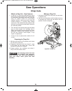
assembly. See dimension drawing – Figure 37.
2. Mark the locations of the support holes on the
wood from the back side of the fence.
3. Drill and countersink the holes on the front of the
support board.
4. Fasten from front of fence: Attach (each) auxiliary
fence using two (2) 3/16" flat head machine
screws. With 3/4" auxiliary fence, use 1-1/2" long
screws. Secure behind metal fence with washer
and machine nuts.
Fasten from back of fence: With 3/4" auxiliary
fence, use 1/4" round head wood screws (3/4"
long). Drill four pilot holes through auxiliary fence
and run screws from rear of metal fence.
5. Make a full depth cut to create the blade slot.
Check for interference between the auxiliary fence
and the lower blade guard. Make adjustments as
necessary.
6. For best splinter-free cuts, use the chop cut
method.
7. When making slide cuts, the center must be
notched out per pattern (see Figure 37).
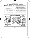
52083<?6;A2?32?2;023?<:.;F
0<:=<;2;A@
64B?2BE696.?F2;02
*%""
!
Flat Head Machine Screws
Blade Slot
Auxiliary
Fence
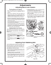
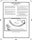
$?2=.?6;43<?&.D#=2?.A6<;@
64B?2'.99BE696.?F*<<12;02'5608
Right Side
1-3/8"
6-3/8"
6-3/8"
NOTCH OUT
1-3/8"
2-1/2"
9.5" 7"
Left Side
5-1/2"
26"
4 Mounting Holes
SLIDE CUT
2-3/4"
2-3/4"
BM 2610027879 07-13_BM 2610027879 07-13.qxp 7/8/13 9:52 AM Page 31