


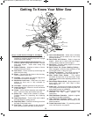
2AA6;4'<;<D,<B?!6A2?&.D
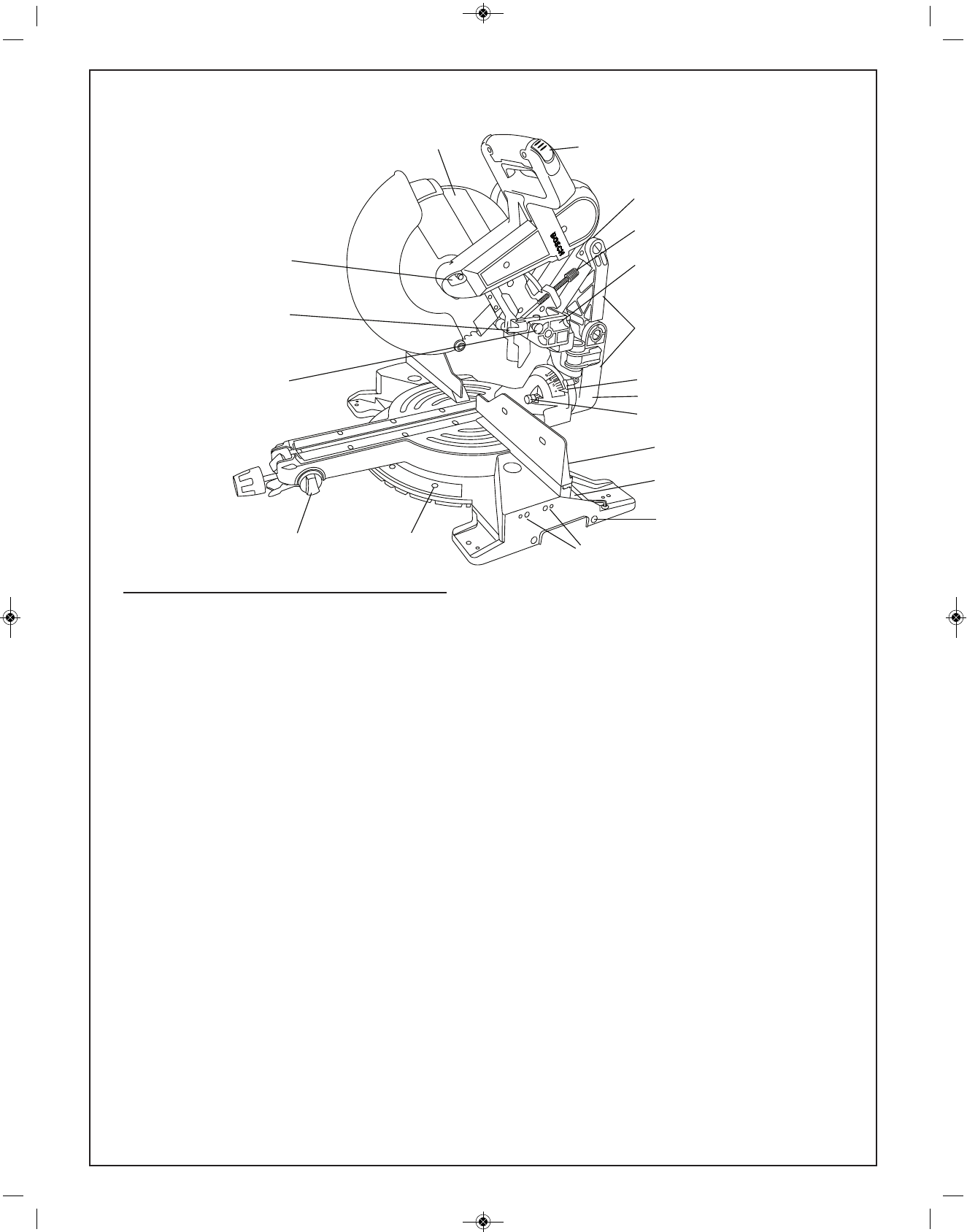
"#''<C62D6A2:@A5?<B45@22=.42
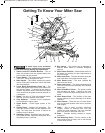
5<=?<D; <08 – Locks head assembly at
intervals for maximum capacity chop cuts in up right
material and crown molding.
<92@3<?#=A6<;.9&9616;4.@2EA2;@6<;@ – For
attaching optional sliding base extension. Provides
extra work support. Useful when cutting long
workpieces.
%B//2? 23920A<? – Attaches to bottom of chute.
Deflects dust into the chute.
B@A5BA2 – Directs sawdust up and through the
elbow and to the bag.
9/<D – Connects the dust chute to the dust bag.
Can be rotated to direct dust.
B@A.4 – Has a zipper at the bottom. Bag can be
uncoupled from elbow for emptying.
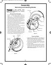
!205.;6@: <08 2C2? – Holds saw in full back
position for chop cuts or fully extended for
transporting.
6;8;</ – Attaches guard link to the pivot post.
<D2?B.?1 6;8 – Allows for smooth movement
of the lower guard.
9.:= – Use to hold the workpiece to the table and
base – insert into clamp post location (item 39).
?B@5 .= – Keeps motor brushes in position.
Provides access for inspecting and replacing
brushes.
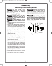
2=A5&A<=&0?2D – Turn the knob end to adjust
the blade depth for cutting grooves.
2=A5&A<=$9.A2 – Plate can be swung out to limit
the depth of the blade travel.
$6C<A$<@A – Provides support for the saw head,
dust collection system and other functional parts.
E6.99612!205.;6@: – Allows saw to smoothly
slide in and out. Can be locked in full rear or fully
extended positions.
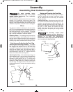
2C29 &0.92 .;1 $<6;A2?@ – Scale is large and
angled - allows user to easily read bevel angles.
Pointer indicates what the current angle is.
2C29$<@A – Provides rotating support for all miter
saw parts above the table.
2C29 2A2;A $6; ?<D; !<916;4 &2AA6;4 –
When engaged, it locks the head assembly to the
bevel angle of 33.9° to the left or right.
9.:=$<@A <0.A6<;@ – Two vertical post holes in
the base – provided to insert the clamp (item 30).
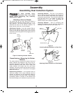
!6A2? 2A2;A $9.A2 &0?2D@ – Four screws
accessible through holes in the miter scale. These
screws are loosened when adjusting position of the
detent plate.
2C29%.;42&2920A<?;</ – Allows selection of 3
bevel ranges: “0-45° Left”, “0-45° Right” or “Max.
Bevel Angle to 47°.”
?/<? <08 – Press arbor lock button to keep blade
from rotating when loosening or tightening arbor bolt
during blade removal or installation.
2.1@@2:/9F <08$6; – Used to lock the head
assembly in the lower position for
transporting.
9612!<C2:2;A<;A?<992?– Adjusts to regulate
movement of the glide mechanism.
.@2 EA2;@6<; 9.:=6;4 ;</@ – Locks the
optional the base extensions (not included) at the
desired positions.
?<D;@A<=:<B;A5<92@– For attaching optional
crown stop supports, see page 55.
1
34
32
35
36
37
38
39
40
41
43
33
42
7
(not shown)
44
(not shown)
22
45
(not shown)
46
BM 2610027879 07-13_BM 2610027879 07-13.qxp 7/8/13 9:52 AM Page 9