


Chapter 3: Installing in a Generic Rack 29
Installing the Stationary Flange Mount in the Rack
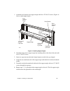
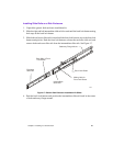
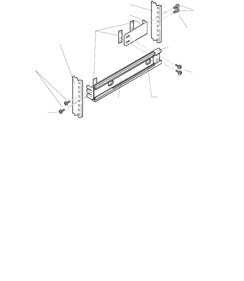
1. Loosely fasten the left side rack mount bracket (use extension bracket if necessary) to
the left side stationary flange mount with two screws and one bar nut*, as shown in
Figure 19. Adjust the length of the stationary flange mount/rack mount bracket
assembly to fit between the front and back channel mounts. Secure the screws holding
the stationary flange mount to the rack mount bracket.
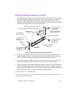
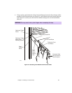
Figure 19. Stationary Flange Mount Slide Assembly
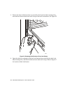
2. Position the intermediate slide rail within the stationary flange mount/rack mount
bracket assembly with the back mating hole farthest from the back lock button, and
center it within the stationary flange mount/rack mount bracket assembly.
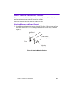
3. Position the stationary flange mount/rack mount bracket assembly on the left side of
the rack just beneath the enclosure location above (load rack from top down).
4. Hold the stationary flange mount/rack mount bracket assembly in a between the front
and back channel mounts. Secure one bar nut with two screws to hold the stationary
flange mount/rack mount bracket assembly in place for the front mounting channel, and
secure one bar nut with two screws for the back mounting channel.
5. Repeat steps 1 - 4 on the right side.
*
If your generic rack has square holes on the channel mounts, contact the original rack manufacturer or your
model shop for installation assistance.
2605
Brass Colored
Bar Nuts
3/8” #10-32 Brass
Colored Pan
Head Screws
3/8” #10-32 Brass
Colored Pan
Head Screws
3/8” #10-32 Brass
Colored Pan
Head Screws
Stationary Flange Mount
Front Channel
Mount Left Side
Front Channel
Mount Mounting
Screws
Back Channel Mount
Mounting Screws
Rack Mount Bracket or Extension Bracket
Back Lock Button
Mating Hole
Back Channel Mount Left Side
Intermediate
Slide Rail