


Chapter 1: Introduction
7
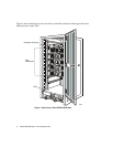
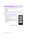
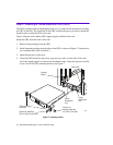
Configuration for Two RAID Systems (AAMK36A2)
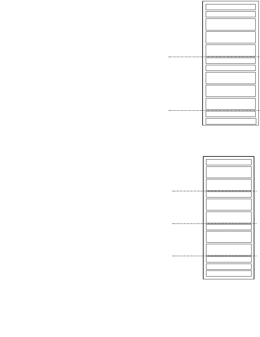
Figure 4 shows a front view of a fully-loaded rack with:
• Filler panels. These should be located as shown in
the figure to guarantee air flow for cooling.
• Two FibreSTORE RAID controller enclosures.
• Disk enclosures. If you are using fewer than three
disk enclosures in any System, leave the slot(s) at
the bottom of that System empty.
• The two Cache Retention Units (CRUs) are always
located at the bottom of the rack.
Figure 4. AAMK36A2
Rack Configuration
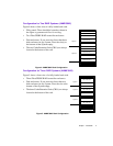
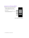
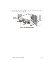
Configuration for Three RAID Systems (AAMK36A3)
Figure 5 shows a front view of a fully-loaded rack with:
• Three FibreSTORE RAID controller enclosures.
• Disk enclosures. If you are using fewer than two
disk enclosures in any System, leave the slot at the
bottom of that System empty
• The three Cache Retention Units (CRUs) are always
located at the bottom of the rack.
Figure 5. AAMK36A3 Rack Configuration
2546.vsd
Disk Enclosure 0
Disk Enclosure 1
Disk Enclosure 2
Disk Enclosure 0
Disk Enclosure 1
Disk Enclosure 2
FibreSTORE RAID
Filler Panel
Panel covering CRU
Panel covering CRU
FibreSTORE RAID
Filler Panel
System 1
System 2
2547.vsd
Disk Enclosure 0
Disk Enclosure 1
Disk Enclosure 0
Disk Enclosure 1
Disk Enclosure 0
Disk Enclosure 1
FibreSTORE RAID
Panel covering CRU
Panel covering CRU
FibreSTORE RAID
FibreSTORE RAID
System 1
System 2
System 3
Panel covering CRU