


BOOK 0958-B
3
SECTION II
INSTALLATION
Before starting the installation, read this section thoroughly. In addition, a thorough review of the Ratings and
Specifications (Section VI) is recommended. The following installation guidelines should be kept in mind when
installing the controller.
INSTALLATION GUIDELINES
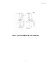
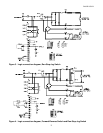
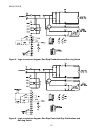
1. CONTROLLER MOUNTING - The controller may be mounted either vertically or horizontally. However, never
mount the controller upside down, immediately beside or above heat generating equipment, or directly below water or
steam pipes.
The controller must be mounted in a location free of vibration.
Multiple controllers may be mounted side by side, as close to each other as the mounting feet will allow.
The minimum clearance at the top and bottom of the controller may be as narrow as the conduit fittings allow.
2. ATMOSPHERE - The atmosphere surrounding the controller must be free of combustible vapors, chemical fumes,
oil vapor, and electrically conductive or corrosive materials.
The air surrounding an enclosed controller must not exceed 40 degrees C (104 degrees F), and the air surrounding an
open-chassis controller must not exceed 55 degrees C (131 degrees F). Minimum air temperature is 0 degree C (32
degrees F) for enclosed and open-chassis controllers.
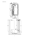
3. CONTROLLER CONSTRUCTION - The controller base is made of die-cast aluminum with a powdered epoxy
finish, and the cover is made of a die-cast aluminum alloy.
The controller enclosure is totally enclosed, non-ventilated, and complies with NEMA Type 4 and 12 standards. There
is an oil resistant synthetic rubber gasket between the cover and base. Those models with integral operator controls
include flexible boots to seal the switches, and a seal for the MOTOR SPEED potentiometer.
4. LINE SUPPLY - The controller should not be connected to a line supply capable of supplying more than 100,000
amperes short-circuit current. Short-circuit current can be limited by using an input supply transformer of 50 KVA or
less, or by using correctly sized current limiting fuses in the supply line ahead of the controller. Do not use a
transformer with less than the minimum transformer KVA listed in Table 8, page 31.
If rated line voltage is not available, a line transformer will be required. If the line supply comes directly from a
transformer, place a circuit breaker or disconnect switch between the transformer secondary and the controller. If power
is switched in the transformer primary, transients may be generated which can damage the controller. See Table 8 (page
31) for minimum transformer KVA.
Do not use power factor correction capacitors on the supply line to the controller.
A 20 Joule metal oxide varistor (MOV) is connected across the controller terminals. If higher energy transients are
present on the line supply, additional transient suppression will be required to limit transients to 150% of peak line
voltage.
When a 115 VAC line supply is used, connect the white (common) wire to Terminal L2 and connect the remaining
(hot) wire to Terminal L1.