


BOOK 0958-B
4
5. ISOLATION TRANSFORMER - While not required, an isolation transformer can provide the following
advantages:
a. Reduce the risk of personal injury if high voltage drive circuits are accidentally touched.
b. Provide a barrier to externally generated AC supply transients. This can prevent controller damage from abnormal
line occurrences.
c. Reduce the potential for damaging current if the motor armature, motor field, or motor wiring becomes grounded.
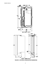
6. GROUNDING - Connect the green or bare (ground) wire of the line supply to the ground screw located near the top
conduit entry hole in the controller base. Then ground the controller base by connecting the ground screw to earth
ground.
The motor frame and operator control stations must also be grounded.
Personal injury may occur if the controller, motor, and operator stations are not properly grounded.
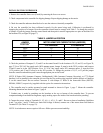
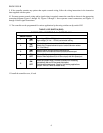
7. WIRING PRACTICES - The power wiring must be sized to comply with the National Electrical Code, CSA, or
local codes. Refer to the controller data label for line and motor current ratings.
Do not use solid wire.
Signal wiring refers to wiring for potentiometers, tachometer generators, and transducers. Control wiring refers to
wiring for operator controls, e.g., switches and pushbuttons. Signal and control wiring may be run in a common
conduit, but not in the same conduit as the power wiring. In an enclosure, signal and control wiring must be kept
separated from power wiring and only cross at a 90 degree angle to reduce electrical noise.
If shielded wire (such as Alpha 2422 - two conductor, 2423 - three conductor, 2424 - four conductor) is used for the
signal and control wiring, connect the shields to chassis ground (ground screw on the controller base) and tape the
opposite ends of the shields. Twisted cable is also suitable for signal and control wiring.
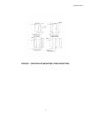
Two 3/4-14 NPT threaded holes are provided for conduit entry, one each in the top and bottom of the controller.