


BOOK 0958-B
34
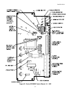
4. MOTOR CONTACTOR - Controller model numbers with an ‘A’ or ‘B’ suffix, e.g., 2331A, 2331AP0, have a DC
magnetic armature contactor, which disconnects both motor armature leads from the controller. An antiplug circuit
ensures that the contactor does not make or break DC.
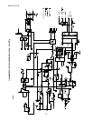
5. POWER CONVERSION - The DC power bridge consists of four SCR’s, one freewheeling diode. Each device is
rated at least 600 PIV. The controller base forms an integral heat sink, with the power devices electrically isolated from
the base.
6. SELECTABLE CAPABILITIES - Switches allow the user to select various modes of operation, as follows:
a. LINE STARTING - By placing SW3:5 in the OFF position, the anti-restart feature will be disabled, and the
controller may be started and stopped with an external AC line contactor. However, a wire jumper must be connected
between TB2-8 and TB2-9. If full speed operation is desired, connect another wire jumper between TB2-2 and TB2-3.
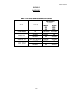
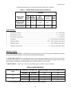
b. TACHOMETER FEEDBACK - To use tachometer feedback with armature feedback backup, connect the
tachometer generator signal to TB2-7 and TB2-5, (polarity insensitive) and select the tachometer generator voltage at
maximum speed by using SW3:1 as follows:
TABLE 13. TACHOMETER FEEDBACK VOLTAGE SELECTION
TACH VOLTAGE SW3:1
8Vdc - 30Vdc ON
31Vdc - 175 Vdc OFF
c. TORQUE REGULATOR - The controller will function as a torque regulator when SW3:3 is OFF. This allows an
external potentiometer to set maximum motor torque (0 - 150% of rated).
7. VOLTAGE TRANSIENT PROTECTION - A metal oxide suppressor (varistor) across the AC line is combined
with RC snubbers across the power bridge to limit potentially damaging high voltage spikes from the AC power source.