


BOOK 0958-B
iv
LIST OF TABLES
TABLE TITLE PAGE
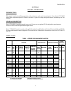
1................... Series 2330 MKII Model Matrix...........................................................................................1
2................... Jumper J4 Position........................................................................................................................5
3.................... Dip Switch (SW3) ........................................................................................................................6
4.................... Initial Potentiometer Settings .....................................................................................................17
5.................... Dynamic Braking Characteristics ..............................................................................................20
6.................... Troubleshooting.................................................................................................................... 25-28
7.................... Parts List, Series 2330 MKII Controllers ..................................................................................29
8.................... Typical Application Data ...........................................................................................................31
9.................... Operating Voltages and Signals.................................................................................................32
10................... Controller Weights .....................................................................................................................32
11................... Speed Regulation Characteristics...............................................................................................33
12................... Shunt Field Data .........................................................................................................................33
13................... Tachometer Feedback Voltage Selection ..................................................................................34
LIST OF ILLUSTRATIONS
FIGURE
TITLE PAGE
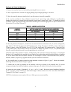
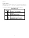
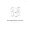
1................... Controller Mounting Configurations .....................................................................................7
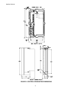
2................... Controller Mounting Dimensions ................................................................................................8
3.................... Logic Connection Diagram, Run-Stop-Jog Switch.....................................................................9
4.................... Logic Connection Diagram, Forward-Reverse Switch and Run-Stop-Jog Switch ....................9
5.................... Logic Connection Diagram, Run-Stop Pushbuttons and Run-Jog Switch ...............................10
6.................... Logic Connection Diagram, Run-Stop-Controlled Stop Pushbuttons and Run-Jog Switch....10
7.................... Logic Connection Diagram, Optional Unidirectional Contactor Using Run-Jog Switch........11
8.................... Logic Connection Diagram, Optional Unidirectional Contactor Using Run-Stop .................11
Pushbuttons and Run-Jog Switch
9.................... Logic Connection Diagram, Optional Armature Contactor Reversing Using Switches..........12
10................... Logic Connection Diagram, Optional Armature Contactor Reversing Using Pushbuttons ....12
and Run-Jog Switch
11................... Logic Connection Diagram, Line Starting With Motor Speed Potentiometer .........................13
12................... Signal Connection Diagram, Motor Speed Potentiometer........................................................13
13................... Signal Connection Diagram, Tachometer Feedback.................................................................14
14................... Signal Connection Diagram, Current (Torque) Reference Potentiometer................................14
15................... Signal Connection Diagram, Line Starting Without a Motor Speed Potentiometer ................14
16................... Signal Connection Diagram, 4-20mA Interface........................................................................15
17................... Signal Connection Diagram, 4-20mA Transducer with Auto/Manual Switch ........................15
18.................. Signal Connection Diagram, Transducer with External Burden Resistor ................................15
19................... Functional Schematic, Series 2330 MKII .................................................................................36
20................... Series 2330 MKII Control Board, 1/6 – 3HP ............................................................................37