BOOK 0958-B
33
Regulation percentages are of motor base speed under steady-state conditions
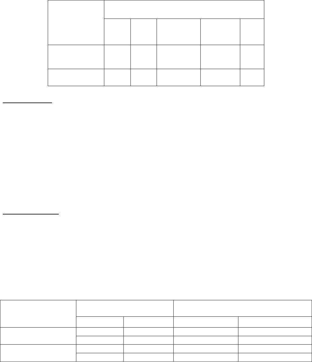
TABLE 11. SPEED REGULATION CHARACTERISTICS
VARIABLE
REGULATION
METHOD
Load
Change
(95%)
Line
Voltage
(±10%)
Field
Heating
(Cold/Normal)
Temperature
(±10
°C)
Speed
Range
Standard Voltage
Feedback with IR
Compensation
2% ±1 % 5 - 12% ±2% 50:1
Optional Speed
(Tach) Feedback
a
0.5% ±1 % 0.2% ±2% 200:1
a. Unidirectional models only.
ADJUSTMENTS
1. Acceleration, Linear ....................................................................................................................0.1 - 30 Seconds
2. Deceleration, Linear ....................................................................................................................0.1 - 30 Seconds
3. IR (Load) Compensation................................................................................................................ 0 - 10% Boost
4. Jog Speed............................................................................................................. 0 - 100% of Motor Base Speed
5. Maximum Speed ............................................................................................50% - 100% of Motor Base Speed
6. Minimum Speed .................................................................................................... 0 - 40% of Motor Base Speed
7. Torque (Current) Limit ........................................................................................ 0 - 150% of Full-Load Torque
SPECIFICATIONS
1. AC LINE PROTECTION - A 100,000 ampere interrupting capacity AC line fuse provides instantaneous protection
from peak loads and fault currents. This line fuse is located inside the controller.
2. AUXILIARY CONTACT - A normally-open Form A relay contact, rated .5 ampere @115 VAC and 2A at 30 VDC,
is available for external use. The relay energizes when a Run command is initiated, and de-energizes when a Normal
Stop command is initiated, the overload monitor trips, or the anti-restart circuit is activated.
3. FIELD SUPPLY - A half-wave or full-wave shunt field supply is available as shown in Table 12;
TABLE 12. SHUNT FIELD DATA
SHUNT FIELD VOLTAGE (VDC) MOTOR SHUNT FIELD LEAD CONNECTIONS
CONTROLLER RATING
(VAC)
Half-Wave
Full-Wave
a
F1 F2
50 F/2
F
115
100 F+
F
100 F/2
F
230
200 F+
F
a. Low inductance motors require a full-wave field to prevent speed instability.
