


BOOK 0958-B
21
REVERSE
To reverse motor rotation on controllers with reversing capabilities, initiate a Stop function and then initiate a
reversing command. The motor will then accelerate to the setting of the MOTOR SPEED potentiometer or external
speed reference signal, as applicable. Forward and reverse speed ranges are identical.
If a FWD-REV switch is used, it must have a center position interlock, which requires a momentary relaxation of
pressure before the opposite position can be engaged. The center position causes a Stop command and allows time for
the motor to stop before a Reverse command is initiated. If a Reverse command is initiated while the motor is rotating,
motor and controller damage may occur.
If Option 1004 (Armature Contactor Reversing With Dynamic Braking) is installed, an antiplug feature prevents
reversing the motor before the motor has stopped.
LOAD MONITOR
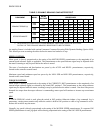
UL approved as a motor protection device. The threshold for inverse timed overload will not exceed 120% of
rated current and will shut down the drive (drop out K0) in about 60 seconds at 150% load current. The drive
may be reset by cycling the enable line, or cycling input line power. Note that the timing capacitor is not reset by
this, and that if the drive is immediately restarted into an overload, it will not take the full time to trip.
CURRENT LOOP TRANSDUCERS
Several onboard features allow easy interfacing to 4-20mA type transducers as well as other current ranges with
appropriate external burden resistors. When SW3 position 2 is closed, an internal 249Ω resistor converts 4-20mA to
a 1-5V input, and SW3 position 4 in the closed position converts the Min Speed Potentiometer to an Input Offset
Potentiometer that allows precise nulling of the zero speed point.
INOPERATIVE MOTOR
If the motor stops and/or won’t start, turn-off the AC supply to the controller, remove the controller cover (if used),
and check the AC line fuse on the controller control board. For the location of the fuse, see Figure 23, page 37. If the
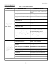
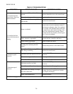
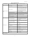
fuse is blown, refer to the Troubleshooting Table (Table 6).