


BOOK 0958-B
17
INITIAL STARTUP
1. Open the controller cover (if used) by removing the four cover screws.
2. Be familiar with all options installed in the controller by reviewing the instruction sheets supplied with the options.
3. Be sure all wiring is correct and all wiring terminations are tightened securely.
4. Be sure the controller is calibrated correctly. See steps 4 and 5 under “Installing The Controller” on page 5.
5. Be sure the AC supply voltage to the controller agrees with the controller data label.
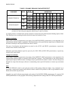
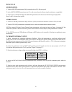
6. The potentiometers in the controller are factory adjusted as shown in Table 4. These settings will provide satisfactory
operation for most applications. If different settings are required, refer to “Adjustment Instructions” starting on page 23
.
TABLE 4. INITIAL POTENTIOMETER SETTINGS
POTENTIOMETER SETTING DESCRIPTION
ACCEL 1/3 Turn Clockwise 10 Seconds
CUR LMT Fully Clockwise (100%) 150% Load
DECEL 1/3 Turn Clockwise 10 Seconds
IR/TACH Fully Counterclockwise (0%) 0% Boost
MAX SPD 3/4 Turn Clockwise 100% Speed
MIN SPD Fully Counterclockwise (0%) 0% Speed
7. If the controller has a cover, place it on the controller and secure it with the four cover screws.
8. Turn-on the AC supply to the controller.
9. Check motor rotation, as follows:
a. If a MOTOR SPEED potentiometer is used, turn it fully counterclockwise. If an external signal is used for the
speed reference, set it at minimum.
b. If a RUN-STOP-JOG switch is used, place it in RUN position. Otherwise, initiate a Run command.
c. Turn the MOTOR SPEED potentiometer clockwise or increase the speed reference signal, as applicable. To stop
the motor, place the switch in STOP position or initiate a Stop command, as applicable.
If the motor rotates in the wrong direction, turn-off the AC supply to the controller, and then interchange the motor
armature leads at the motor connection box or at the controller terminal board.
10. Refer to Section III, “Operation” for operating instructions.