


BOOK 0958-B
6
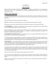
9. If the controller contains any options that require external wiring, follow the wiring instructions in the instruction
sheet supplied with the option.
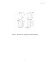
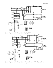
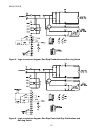
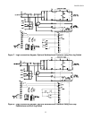
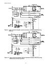
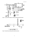
10. If remote operator control wiring and/or signal wiring is required, connect the controller as shown in the appropriate
connection diagram (Figures 3 through 18). Figures 3 through 11 show operator control connections, and Figures 12
through 18 show signal connections.
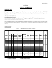
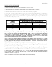
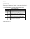
11. The controller can be programmed for various applications by throwing switches on dip switch SW3
TABLE 3. DIP SWITCH (SW3)
FACTORY DEFAULT SETTING IS ALL SWITCHES “ON”
Switch Position
1
ON
OFF
Low voltage (3Vdc - 30Vdc) tachometer scaling
High voltage (31 Vdc - 175Vdc) tachometer scaling.
2
ON
OFF
Selects internal burden resistor for 4-20ma input.
Selects 0 to 5V speed reference input or external burden resistor
(i.e. 10 to 50ma)
3
ON
OFF
Selects internal current (torque) reference pot.
Selects use of an external current (torque) reference pot.
4
ON
OFF
Selects Min Speed pot adjustment.
Selects Offset adjustment (for 4-20ma input) with Min Speed pot.
5
ON
OFF
Selects anti-restart mode. Prevents controller from restarting
automatically after an AC line power interruption.
Disables anti-restart mode. Used for line starting applications
(jumper TB2:9 to TB2:8 to enable drive).
12. Install the controller cover, if used.