


BOOK 0958-B
27
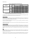
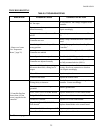
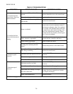
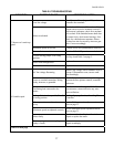
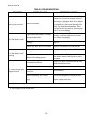
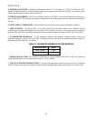
TABLE 6. TROUBLESHOOTING
INDICATION POSSIBLE CAUSE CORRECTIVE ACTION
Low line voltage
Check for rated line voltage, ±10%, on the
controller line terminals.
Motor overloaded
Check shunt field current.
a
Low shunt field
current causes excessive armature current. If
field current is adequate, check for a mechani
cal overload. If the unloaded motor shaft does
not rotate freely, check motor bearings. Also
check for a shorted motor armature. Motor
overload can also be caused by incorrect gear
ratio. Correct accordingly.
Maximum speed set too low Turn the MAX SPD potentiometer clockwise.
Current limit set too low Turn the CUR LMT potentiometer clockwise.
Current scaling jumper J4 in wrong
position
See Step 4 and Table 2 on page 5.
Motor field demagnetized
b
Replace the motor.
7. Motor won’t reach top
speed
Control board failure Replace the control board.
AC line voltage fluctuating
Observe line voltage with a voltmeter or oscil
loscope. If fluctuations occur, correct condi
tion accordingly.
Loose or corroded connection. Wiring
faulty, incorrect, or grounded
Check all terminals, connections, and wiring
between the line, operator controls, controller,
and motor.
Oscillating load connected to the
motor
Stabilize the load. Turning the IR/TACH
potentiometer counterclockwise may mini
mize oscillations.
Voltage Selection Jumpers J1, J2 or J3
in wrong position
See Step 5 on page 5 under, “Installing The
Controller.”
IR compensation not adjusted cor-
rectly
See the IR Compensation adjustment instruc
tions on page 23.
Maximum speed not adjusted correctly
See the Maximum Speed adjustment instruc
tions on page 23.
Motor faulty
Check motor brushes. Replace if needed.
Repair or replace the motor.
8. Unstable speed
Tachometer generator or coupling
faulty (if used)
Repair accordingly.
Cont’d on next page