


BOOK 0958-B
32
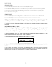
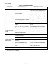
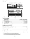
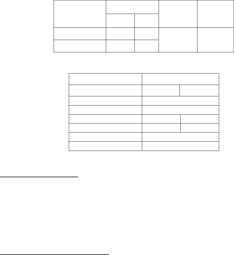
TABLE 9. OPERATING VOLTAGES AND SIGNALS
OUTPUT VDC
POWER SOURCE
(Single-phase)
Armature Field
SPEED
REFERENCE
SIGNAL
MAGNETIC
CONTROL
VOLTAGE
115V, 50 or 60 Hz 0 - 90 50/100
230V, 50 or 60 Hz 0 - 180 100/200
0 -5 Vdc
0 - 10 Vdc
4 - 20Ma
24 VDC
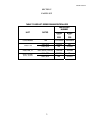
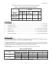
TABLE 10. CONTROLLER WEIGHTS
CONTROLLER MODEL WEIGHT - LBS (KG)
Rated Horsepower (HP) 1/6 - 2 3
2331, 2332, 2336 3.25 (1.48)
2331A, 2332A, 2336A 3.80 (1.75)
2331P0, 2331P1, 2331P2 5.50 (2.50) NA
2331AP0, 2331AP3 6.05 (2.75) NA
2335 0.90 (0.42)
2335A, 1.70 (0.77)
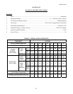
OPERATING CONDITIONS
1. Altitude, Standard ........................................................................................ 1000 Meters (3300 Feet) Maximum
1
2. Ambient Temperature..................................................................................................... 0 - 40°C (32°F - 104°F)
2
3. Line Frequency Variation ............................................................................................................ ± 2 Hz Of Rated
4. Line Voltage Variation ..................................................................................................................±10% Of Rated
5. Relative Humidity................................................................................................................. 95% Noncondensing
PERFORMANCE CHARACTERISTICS
1. Controlled Speed Range ...................................................................................................0 To Motor Base Speed
2. Displacement Power Factor (Rated Speed/Rated Load)................................................................................. 87%
3. Efficiency (Rated Speed/Rated Load)
a. Controller Only............................................................................................................................................... 98%
b. Controller With Motor, Typical................................................................................................................. 85%
4. Speed Regulation...............................................................................................................................See Table 11
1. Controller can be derated by 1% per 100 meters to operate at higher altitudes.
2. 55°C (131°F) maximum in enclosed areas where open-chassis controllers are mounted.