


BOOK 0958-B
5
INSTALLING THE CONTROLLER
1. Remove the controller front cover (if used) by removing the four cover screws.
2. Check components in the controller for shipping damage. Report shipping damage to the carrier.
3. Check the controller and motor data labels to be sure the units are electrically compatible.
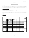
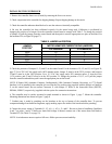
4. Be sure the controller has been calibrated correctly for the motor being used. Calibration is performed by
changing the position of a Jumper J4 on the controller control board to comply with Table 2. To change the position
of Jumper J4, pull the jumper from the control board and then push it onto the appropriate two pins on the board. For
the location of J4, see Figure 20 (page 37).
TABLE 2. JUMPER J4 POSITION
MOTOR ARMATURE CURRENT RATING (AMPERES)
JUMPER
POSITION
a
2 HP Maximum 3 HP Maximum
100% 10 15
80% 8 12
60% 6 9
40% 4 6
20% 2 3
a. Select the position closest to the motor nameplate armature current rating.
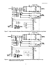
5. Check the positions of Jumpers J1, J2, and J3 on the control board. For the locations of J1, J2, and J3, see Figure 20,
page 37. For a 230 VAC line supply and a 180V armature motor, Jumper J1 must be in the 230V position, and Jumpers
J2 and J3 must be in the 180V position. For a 115 VAC line supply and a 90V armature motor, J1 must be in the
115V position, and J2 and J3 must be in the 90V position. To change the position of J1, J2, or J3 pull the jumper
from the control board and then push it onto the appropriate pins on the board.
NOTE: If Option 1001 (Armature Contactor, Unidirectional), 1004 (Armature Contactor, Reversing), or 1775 (Signal
Interface) is to be installed in the controller, do not offset the five-position plug (supplied with the option) at Connector
J1 on the control board. Do not confuse Connector J1 with Jumper J1. Refer to the Instruction Sheet (ISP0703,
ISP0666, ISP0653, respectively) supplied with the option for connection instructions.
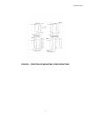
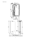
6. The controller may be surface mounted or panel mounted as shown in Figure 1, page 7. Mount the controller.
Mounting dimensions are shown in Figure 2, page 8.
7. Conduit entry is made by punching out the knockout at the top or bottom of the controller base. To prevent
component damage from knockout fragments, apply masking tape to the inside of the knockout before punching.
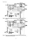
8. Connect the power wiring to Terminals L1, L2, A1 (+), A2 (-), F+ and F-. Be sure to observe Installation Guidelines
4 and 7 on pages 3 and 4. If half-wave shunt field voltage is desired, connect one of the motor shunt field leads to
Terminal F/2 (see Table 12 on page 33).
NOTE: Low inductance motors require a full-wave field to prevent current instability.