


BOOK 0958-B
25
TROUBLESHOOTING
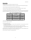
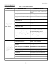
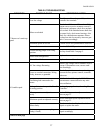
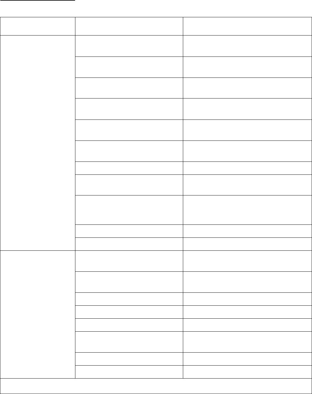
TABLE 6. TROUBLESHOOTING
INDICATION POSSIBLE CAUSE CORRECTIVE ACTION
AC line open
Be sure rated AC line voltage is applied to the
controller.
Operator controls inoperative or con-
nected incorrectly
Repair accordingly.
Open circuit between Connectors E1
and E2
A wire jumper or switch must connect E1 to
E2.
Controller not reset
Initiate a Stop command and then a Start com-
mand.
Line Voltage Selection Jumper J1 in
wrong position
See Step 5 on page 5 under, “Installing The
Controller.”
Controller not enabled
Be sure +24 VDC is applied to Terminal TB2
8.
Loss of speed reference signal Check for 0 - 10 VDC speed reference signal.
Controller not adjusted correctly
Turn the ACCEL and CUR LMT potentiome
ters fully counterclockwise (100%).
Open shunt field winding or wiring to
the motor shunt field, causing loss of
torque
a
Check the motor shunt field and associated
circuitry for a loose connection or a broken
wire. Repair accordingly.
Motor failure Repair or replace the motor.
1. Motor won’t start
(See “Inoperative
Motor,” page 21)
Control board failure Replace the control board.
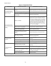
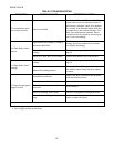
Wiring faulty or incorrect
Check all external wiring terminating in the
controller. Correct accordingly.
Circuit, component, or wiring
grounded
Remove ground fault.
SCR1, SCR2, SCR3 or SCR4 shorted Replace shorted SCR’s or the control board.
Bridge Diode D1b shorted Replace shorted diode or the control board.
Varistor RV1 shorted Replace RV1 or the control board.
Shunt Field Diode D39, D40, D41, or
D42 shorted
a
Replace shorted diode or the control board.
Motor shunt field shorted or grounded
a
Repair or replace the motor.
2. Controller line fuse
blows when AC line
power is applied to the
controller
Control board failure Replace the control board.
Cont’d on next page