


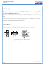
DIGITAL OUTPUTS
11 - 4
ETC00781(4) Series 100 e 02/2004
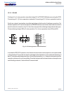
VALVE CONTROL / STATUS SIGNALS (OPTION)
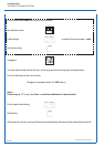
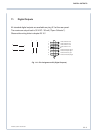
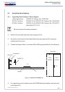
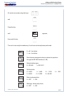
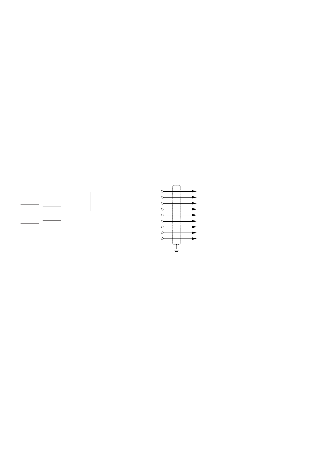
Fig. 11-2: Pin Assignments X 1 (Status Signals)
11.2 Valve Control
Optional external solenoid valves have to be connected to plug X 3 on the rear panel to be
controlled by the analyzer. Observe the wiring hints in chapter 29.10 !
11.3 Status Signals (Option non-voltage-carrying relay contacts)
Three optional status signals are available on the 9 pin subminiature D plug X 1 on the rear
panel of the analyzer (see chapter 7.4, 9. and 13., too).
These signals are floating contacts with a maximum load of 30 V / 1 A / 30 W !
Observe the wiring hints in chapter 29.10 !
*)
BINOS
®
100 2M/F with software revision 5.0 or higher only
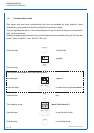
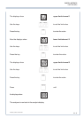
1 OK (open) / Failure (closed)
2 OK (closed) / Failure (open)
3 Measure (open) / Calibration (closed)
4 Measure (closed) / Calibration (open)
5 Pump OFF (open) / Pump ON (closed)
*)
6 OK / Failure (Common)
7 Measure / Calibration (Common)
8 Gas sampling pump (Common)
*)
9 Pump OFF (closed) / Pump ON (open)
*)
9
6
5
1
1
5
6 9