


PREPARATION
5 - 5
ETC00781(4) Series 100 e 02/2004
5.3 Gas Connections
The installed gas connections are depending on gas analyzer specification and model. All
fittings are clearly marked.
The fittings are located on the rear panel of the instrument or on the left bottom side.
The exhaust gas lines have to be mounted in a declining, pressureless
and frost-free way and according to the valid emission legislation !
Do not interchange gas inlets and gas outlets !
Ensure that all gas connections are made as labeled and are leak free !
Improper gas connections could result in explosion and death !
The unit´s exhaust may contain hydrocarbons and other toxic gases such as
carbon monoxide ! Carbon monoxide is highly toxic !
Permissible gas pressure max. 1,500 hPa !
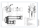
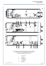
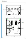
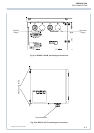
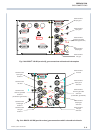
5.3.1 Standard Configuration
Depending on analyzer version the following gas connections are installed:
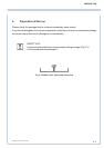
in = Gas inlet out = Gas outlet
K 1 = measuring channel 1 K 2 = measuring channel 2
*)
Zero gas and span gas are introduced directly via the sample gas inlet. The test gas containers
have to be set up according to the current legislation.
Be sure to observe the safety regulations for the respective gases
(sample gas and test gases / span gases) and the gas bottles !
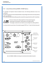
*)
for HYDROS
®
100 with open reference side of sensor the gas fittings of channel 2 are used to
connect the reference gas.
GAS CONNECTIONS