


PLUG PIN ALLOCATION OF PRINTED CIRCUIT BOARDS
18 - 6
ETC00781(1) Series 100 e 10/2001
Rosemount Analytical
P 2
1
P 18
orange
blue
green
yellow
1
P 16
1
P 10
P 15
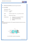
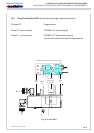
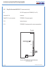
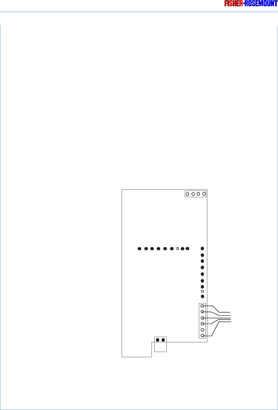
PLUG PIN ALLOCATION OF WAP 100 (TC MEASURMENT)
18.3 Plug Pin Allocation WAP 100 (TC measurement only)
P2 24 V DC supply from PCB BKS (P1 or P2)
Terminals P 18 to sensor
Cable P15, 5 - pin connector PCB BKS, X 5 (sensor signal)
P 16 heater of sensor
P 10 PCB BSE 01 (analog input for cross compensation)
Fig. 18-3: PCB “WAP 100”, Plug Pin Allocation
(principle drawing)