


DIGITAL INPUTS / FOUNDATION
™
FIELDBUS (OPTIONS)
13 - 1
ETC00781(4) Series 100 e 02/2004
13. Digital Inputs / Foundation
™
Fieldbus (BINOS
®
100 2M/F option only)
Be sure to observe the safety measures for all workings at the analyzer!
13.1 Digital Inputs
13.1.1 General
To remotely control different conditions of analyzer BINOS
®
100 2M/F, the analyzer can
optionally be equipped with 7 digital inputs . They are available at terminals on the rear side
of the analyzer (Fig. 1-8, Item 9). The inputs are active only if the analyzer is equipped with built-
in solenoid valve block or if the solenoid valves are connected to the digital outputs (see
chapter 29.5.1). Observe the wiring hints in chapter 29.10 !
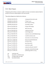
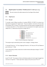
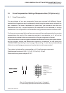
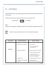
Fig. 13-1: Terminal assignments “Digital Inputs”
The analyzer may be controlled by either control voltages or floating contacts.
A “low signal” has to be < 1.4 V dc, a“high signal” has to be > 3.5 V dc (max. 30 V dc). Reference
point is terminal “V-” (
⊥⊥
⊥⊥
⊥).
To work with floating contacts, customer can use the intrinsic-safe output voltage of “+ 5 V DC”
at terminal “V+”.
13.1.2 Start of Calibration
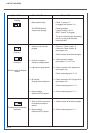
Inputs “E1 to E3”: The analyzer will start a calibration procedure if control signal changes from
“low-level” to “high-level”. These inputs have a higher priority than inputs “E4 to E7”
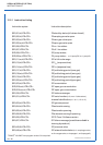
DIGITAL INPUTS
E3
E2
E1
E4
E5
E7
E6
V-
V+
+ 5 V DC
⊥⊥
⊥⊥
⊥
start zero calibration channel 1 & 2
start span calibration channel 1
start span calibration channel 2
open zero gas valve
open span gas valve 1
open span gas valve 2
close sample gas valve / sample gas pump off