


1 - 9
TECHNICAL DESCRIPTION
ETC00781(4) Series 100 e 02/2004
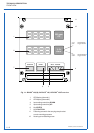
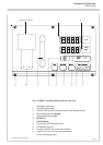
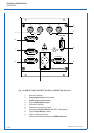
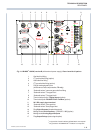
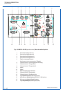
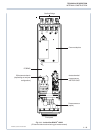
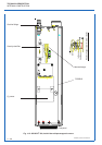
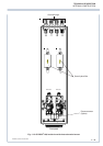
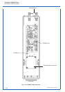
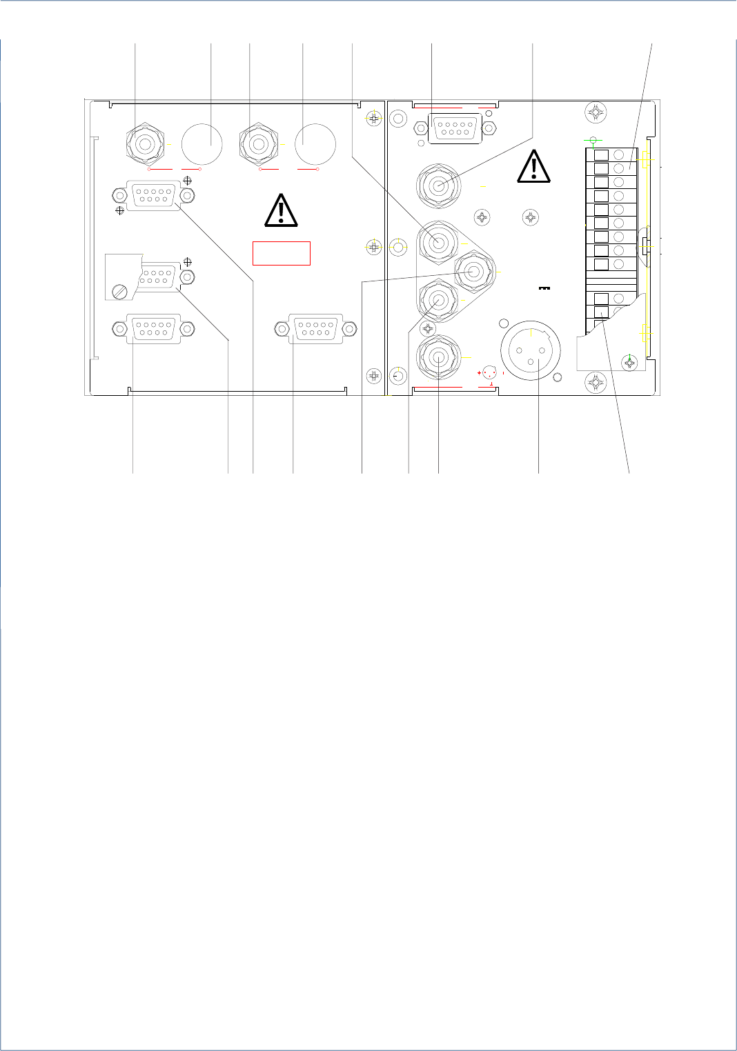
Fig. 1-8: BINOS
®
100 2M, version B (with external power supply), Rear view with all options
1 Gas inlet line fitting
22
nd
gas inlet line fitting (option)
3 Gas outlet line fitting
42
nd
gas outlet line fitting (option)
5 Plug for analog signal inputs
(interference cross compensation, TC only)
6 “Solenoid valves”: common gas outlet line fitting
7 “Solenoid valves”: Test gas inlet 1
8 “Solenoid valves”: Test gas inlet 2
9 Terminal strips for the 7 Digital Inputs (option)
10 Terminal strips for FOUNDATION
™
Fieldbus (option)
*)
11 24 V DC supply input terminal
12 “Solenoid valves”: Zero gas inlet
13 “Solenoid valves”: Sample gas inlet
14 Plug Digital Outputs (threshold contacts)
15 Mating socket Serial Interface
**)
[RS 232 C / 485] (option)
16 Mating socket Analog Signal Outputs
17 Plug Output Relays (status signal option)
*)
only possible if serial interface RS 232/485 is not request !
**)
only possible if FOUNDATION
™
Fieldbus is not request !
REAR PANEL
OUT
SPAN 2
SPAN 1
ANALOG IN
3
2
1
ZERO
SAMPLE
24V
max.120W
FB-
FB-
FB+
FB+
E3
E2
E1
E4
E5
E7
E6
V-
V+
DIGITAL IN
DURCHFLUSS
MAX. 1 L/MI N
IN/OUT
X1 OUTPUT
X2 OUTPUT X3 OUTPUT
IN OUT
K1 K2 K1 K2
1234 5
6
87
16 15 17 14 13 12
9
1011
FLOW