


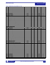
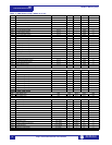

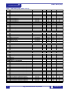

Modbus Memory Map
489
Communications Guide
http://www.GEindustrial.com/multilin
9
GE Multilin
Modbus Memory Map
Memory Map
Information
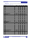
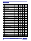
The data stored in the 489 is grouped as Setpoints and Actual Values. Setpoints can
be read and written by a master computer. Actual Values are read only. All Setpoints
and Actual Values are stored as two byte values. That is, each register address is
the address of a two-byte value. Addresses are listed in hexadecimal. Data values
(Setpoint ranges, increments, and factory values) are in decimal.
Many Modbus communications drivers add 40001d to the actual address of the
register addresses. For example: if address 0h was to be read, 40001d would be the
address required by the Modbus communications driver; if address 320h (800d) was
to be read, 40801d would be the address required by the Modbus communications
driver.
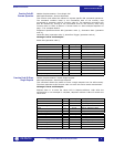
User-Definable
Memory Map Area
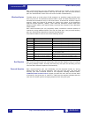
The 489 contains a User Definable area in the memory map. This area allows
remapping of the addresses of all Actual Values and Setpoints registers. The User
Definable area has two sections:
1. A Register Index area (memory map addresses 0180h to 01FCh) that contains
125 Actual Values or Setpoints register addresses.
2. A Register area (memory map addresses 0100h to 017Ch) that contains the
data at the addresses in the Register Index.
Register data that is separated in the rest of the memory map may be remapped to
adjacent register addresses in the User Definable Registers area. This is
accomplished by writing to register addresses in the User Definable Register Index
area. This allows for improved throughput of data and can eliminate the need for
multiple read command sequences.
For example, if the values of Average Phase Current (register addresses 0412h and
0413h) and Hottest Stator RTD Temperature (register address 04A0h) are required
to be read from an 489, their addresses may be remapped as follows:
1. Write 0412h to address 0180h (User Definable Register Index 0000) using func-
tion code 06 or 16.
2. Write 0413h to address 0181h (User Definable Register Index 0001) using func-
tion code 06 or 16.
(Average Phase Current is a double register number)
3. Write 04A0h to address 0182h (User Definable Register Index 0001) using func-
tion code 06 or 16.
A read (function code 03 or 04) of registers 0100h (User Definable Register 0000)
and 0101h (User Definable Register 0001) will return the Average Phase Current
and register 0102h (User Definable Register 0002) will return the Hottest Stator
RTD Temperature.
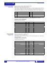
Event Recorder The 489 event recorder data starts at address 3000h. Address 3003h is the ID
number of the event of interest (a high number representing the latest event and a
low number representing the oldest event). Event numbers start at zero each time
the event record is cleared, and count upwards. To retrieve event 1, write ‘1’ to the
Event Record Selector (3003h) and read the data from 3004h to 30E7h. To retrieve
event 2, write ‘2’ to the Event Record Selector (3003h) and read the data from
3004h to 30E7h. All 40 events may be retrieved in this manner. The time and date
stamp of each event may be used to ensure that all events have been retrieved in
order without new events corrupting the sequence of events (event 0 should be less
recent than event 1, event 1 should be less recent than event 2, etc.).
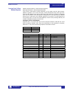
If more than 40 events have been recorded since the last time the event record was
cleared, the earliest events will not be accessible. For example, if 100 events have
been recorded (i.e., the total events since last clear in register 3002h is 100),
events 60 through 99 may be retrieved. Writing any other value to the event record
selector (register 3003h) will result in an “invalid data value” error.
NOTE