


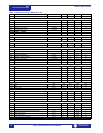
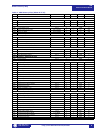
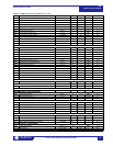
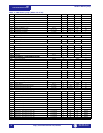


Modbus Memory Map
489
Communications Guide
http://www.GEindustrial.com/multilin
21
GE Multilin
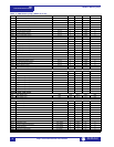
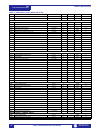
12B2 Input Name 0 to 12 1 – F22 _
12B8 Block Input From Online 0 to 5000 1 s F1 0
12B9 General Input F Control 0 to 1 1 – F105 0
12BA Pulsed Control Relay Dwell Time 0 to 250 1 s F2 0
12BB Assign Control Relays (1-5) 0 to 4 1 – F50 0
12BC General Input F Control Events 0 to 1 1 – F105 0
12BD General Input F Alarm 0 to 2 1 – F115 0
12BE Assign Alarm Relays (2-5) 1 to 4 1 – F50 16
12BF General Input F Alarm Delay 1 to 50000 1 s F2 50
12C0 General Input F Alarm Events 0 to 1 1 – F105 0
12C1 General Input F Trip 0 to 2 1 – F115 0
12C2 Assign Trip Relays (1-4) 0 to 3 1 – F50 1
12C3 General Input F Trip Delay 1 to 50000 1 s F2 50
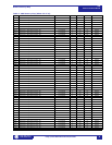
DIGITAL INPUTS / GENERAL INPUT G
12D0 Assign Digital Input 0 to 7 1 – F210 0
12D1 Asserted Digital Input State 0 to 1 1 – F131 0
12D2 Input Name 0 to 12 1 – F22 _
12D8 Block Input From Online 0 to 5000 1 s F1 0
12D9 General Input G Control 0 to 1 1 – F105 0
12DA Pulsed Control Relay Dwell Time 0 to 250 1 s F2 0
12DB Assign Control Relays (1-5) 0 to 4 1 – F50 0
12DC General Input G Control Events 0 to 1 1 – F105 0
12DD General Input G Alarm 0 to 2 1 – F115 0
12DE Assign Alarm Relays (2-5) 1 to 4 1 – F50 16
12DF General Input G Alarm Delay 1 to 50000 1 s F2 50
12E0 General Input G Alarm Events 0 to 1 1 – F105 0
12E1 General Input G Trip 0 to 2 1 – F115 0
12E2 Assign Trip Relays (1-4) 0 to 3 1 – F50 1
12E3 General Input G Trip Delay 1 to 50000 1 s F2 50
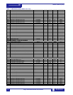
DIGITAL INPUTS / REMOTE RESET
1300 Assign Digital Input 0 to 7 1 – F210 0
DIGITAL INPUTS / TEST INPUT
1310 Assign Digital Input 0 to 7 1 – F210 0
DIGITAL INPUTS / THERMAL RESET
1320 Assign Digital Input 0 to 7 1 – F210 0
DIGITAL INPUTS / DUAL SETPOINTS
1340 Assign Digital Input 0 to 7 1 – F210 0
1341 Active Setpoint Group 0 to 1 1 – F118 0
1342 Edit Setpoint Group 0 to 1 1 – F118 0
DIGITAL INPUTS / SEQUENTIAL TRIP
1360 Assign Digital Input 0 to 7 1 – F210 0
1361 Sequential Trip Type 0 to 1 1 – F206 0
1362 Assign Trip Relays (1-4) 0 to 3 1 – F50 1
1363 Sequential Trip Level 2 to 99 1 × Rated MW F14 5
1365 Sequential Trip Delay 2 to 1200 1 s F2 10
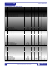
DIGITAL INPUTS / FIELD-BREAKER DISCREPANCY
1380 Assign Digital Input 0 to 7 1 – F210 0
1381 Field Status Contact 0 to 1 1 – F109 0
1382 Assign Trip Relays (1-4) 0 to 3 1 – F50 1
1383 Field-Breaker Discrepancy Trip Delay 1 to 5000 1 s F2 10
DIGITAL INPUTS / TACHOMETER
13A0 Assign Digital Input 0 to 7 1 – F210 0
13A1 Rated Speed 100 to 3600 1 RPM F1 3600
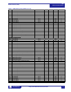
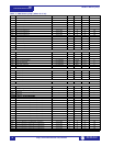
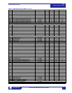
Table 1: 489 Memory Map (Sheet 11 of 29)
ADDR NAME RANGE STEP UNITS FORMAT DEFAULT
1, 2, 3 See Table footnotes on page 39