


DNP Point Lists489
Communications Guide
http://www.GEindustrial.com/multilin
56
GE Multilin
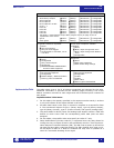
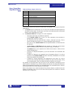
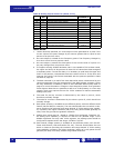
TABLE NOTES:
1. Unless otherwise specified, an event object will be generated for a point if the
current value of the point changes by an amount greater than or equal to two
percent of its previous value.
2. An event object is created for the Frequency point if the frequency changes by
0.04 Hz or more from its previous value.
3. An event object is created for these points if the current value of a point is in
any way changed from its previous value.
4. To support existing SCADA hardware that is not capable of 32-bit data reads,
the upper and lower 16-bit portions of these 32-bit values have been assigned
to separate points. To read this data, it is necessary to read both the upper and
lower 16-bit portions, concatenate these two values to form a 32-bit value and
interpret the result in the format associated with the point as specified in Data
Formats on page 40.
5. The data returned by a read of the User Map Value points is determined by the
values programmed into the corresponding User Map Address registers (which
are only accessible via Modbus). Refer to User-Definable Memory Map Area on
page 9 for more information. Changes in User Map Value points never generate
event objects. Note that it is possible to refer to a 32-bit quantity in a user map
register, which may require the use of a 32-bit variation to read the associated
analog input point.
6. The scale for pre-trip currents is determined by the value in point 9, which
should not normally change
7. The scale for currents is determined by the value in point 47, which should not
normally change
8. Each power quantity is available at two different points, with two different scale
factors (kW and MW, for example). The user should select the unit which is clos-
est to providing the resolution and range desired. If 32-bit analog input capabil-
ity is present, the higher-resolution (kW, kvar, kVA) points should generally be
used, since they provide the greatest resolution.
9. Analog input values may be –50000 to +50000 if so configured. Therefore, 32-
bit analog input capability is required to read the full possible range. If the
SCADA equipment can only read 16-bit registers, the analog inputs should be
configured to operate within the range –32768 to +32767.
10. Each neutral voltage quantity is available at two different points, with two dif-
ferent scale factors (volts and tenths of a volt). The user should select the unit
which is closest to providing the resolution and range desired. If 32-bit analog
input capability is present, the higher-resolution (tenths of a volt) points should
generally be used, since they provide the greatest resolution.
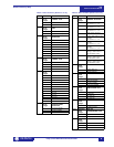
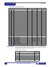
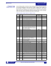
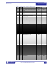
121 F1 Average Negative Sequence Current Class 2
122 F1 Average Phase-Phase Voltage Class 2
123 - User Map Value 1 Note 5
124 - User Map Value 2 Note 5
↓↓…↓... ↓ ↓
246 - User Map Value 124 Note 5
247 - User Map Value 125 Note 5
248 F118 Active Setpoint Group Class 1 Note 3
249 F13 Positive kWh Class 2
250 F13 Positive kvarh Class 2
251 F13 Negative kvarh Class 2
252 F12 Generator Hours Online Class 2
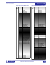
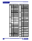
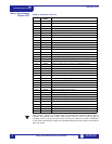
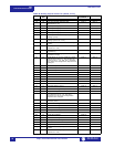
Table 8: Analog Inputs Point List (Sheet 4 of 4)
INDEX FOR-
MAT
DESCRIPTION EVENT CLASS
ASSIGNED TO
NOTES