


Modbus Memory Map489
Communications Guide
http://www.GEindustrial.com/multilin
20
GE Multilin
1242 Assign Trip Relays (1-4) 0 to 3 1 – F50 1
1243 General Input B Trip Delay 1 to 50000 1 s F2 50
DIGITAL INPUTS / GENERAL INPUT C
1250 Assign Digital Input 0 to 7 1 – F210 0
1251 Asserted Digital Input State 0 to 1 1 – F131 0
1252 Input Name 0 to 12 1 – F22 _
1258 Block Input From Online 0 to 5000 1 s F1 0
1259 General Input C Control 0 to 1 1 – F105 0
125A Pulsed Control Relay Dwell Time 0 to 250 1 s F2 0
125B Assign Control Relays (1-5) 0 to 4 1 – F50 0
125C General Input C Control Events 0 to 1 1 – F105 0
125D General Input C Alarm 0 to 2 1 – F115 0
125E Assign Alarm Relays (2-5) 1 to 4 1 – F50 16
125F General Input C Alarm Delay 1 to 50000 1 s F2 50
1260 General Input C Alarm Events 0 to 1 1 – F105 0
1261 General Input C Trip 0 to 2 1 – F115 0
1262 Assign Trip Relays (1-4) 0 to 3 1 – F50 1
1263 General Input C Trip Delay 1 to 50000 1 s F2 50
DIGITAL INPUTS / GENERAL INPUT D
1270 Assign Digital Input 0 to 7 1 – F210 0
1271 Asserted Digital Input State 0 to 1 1 – F131 0
1272 Input Name 0 to 12 1 – F22 _
1278 Block Input From Online 0 to 5000 1 s F1 0
1279 General Input D Control 0 to 1 1 – F105 0
127A Pulsed Control Relay Dwell Time 0 to 250 1 s F2 0
127B Assign Control Relays (1-5) 0 to 4 1 – F50 0
127C General Input D Control Events 0 to 1 1 – F105 0
127D General Input D Alarm 0 to 2 1 – F115 0
127E Assign Alarm Relays (2-5) 1 to 4 1 – F50 16
127F General Input D Alarm Delay 1 to 50000 1 s F2 50
1280 General Input D Alarm Events 0 to 1 1 – F105 0
1281 General Input D Trip 0 to 2 1 – F115 0
1282 Assign Trip Relays (1-4) 0 to 3 1 – F50 1
1283 General Input D Trip Delay 1 to 50000 1 s F2 50
DIGITAL INPUTS / GENERAL INPUT E
1290 Assign Digital Input 0 to 7 1 – F210 0
1291 Asserted Digital Input State 0 to 1 1 – F131 0
1292 Input Name 0 to 12 1 – F22 _
1298 Block Input From Online 0 to 5000 1 s F1 0
1299 General Input E Control 0 to 1 1 – F105 0
129A Pulsed Control Relay Dwell Time 0 to 250 1 s F2 0
129B Assign Control Relays (1-5) 0 to 4 1 – F50 0
129C General Input E Control Events 0 to 1 1 – F105 0
129D General Input E Alarm 0 to 2 1 – F115 0
129E Assign Alarm Relays (2-5) 1 to 4 1 – F50 16
129F General Input E Alarm Delay 1 to 50000 1 s F2 50
12A0 General Input E Alarm Events 0 to 1 1 – F105 0
12A1 General Input E Trip 0 to 2 1 – F115 0
12A2 Assign Trip Relays (1-4) 0 to 3 1 – F50 1
12A3 General Input E Trip Delay 1 to 50000 1 s F2 50
DIGITAL INPUTS / GENERAL INPUT F
12B0 Assign Digital Input 0 to 7 1 – F210 0
12B1 Asserted Digital Input State 0 to 1 1 – F131 0
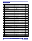
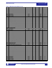
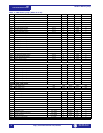
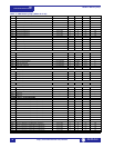
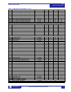
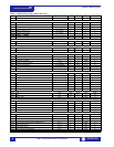
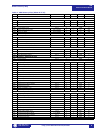
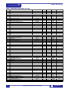
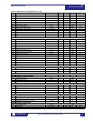
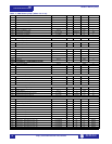
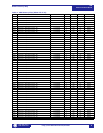
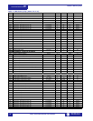
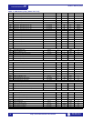
Table 1: 489 Memory Map (Sheet 10 of 29)
ADDR NAME RANGE STEP UNITS FORMAT DEFAULT
1, 2, 3 See Table footnotes on page 39