


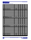

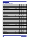

Modbus Memory Map
489
Communications Guide
http://www.GEindustrial.com/multilin
19
GE Multilin
1138 Clear Breaker Information 0 to 1 1 – F103 0
SYSTEM SETUP / CURRENT SENSING
1180 Phase CT Primary 10 to 50001 1 Amps F1 50001
1181 Ground CT 0 to 3 1 – F104 0
1182 Ground CT Ratio 10 to 10000 1 : 1 / :5 F1 100
SYSTEM SETUP / VOLTAGE SENSING
11A0 VT Connection Type 0 to 2 1 – F106 0
11A1 Voltage Transformer Ratio 100 to 30000 1 : 1 F3 500
11A2 Neutral VT Ratio 100 to 24000 1 : 1 F3 500
11A3 Neutral Voltage Transformer 0 to 1 1 – F103 0
SYSTEM SETUP / GEN. PARAMETERS
11C0 Generator Rated MVA 50 to 2000001 1 MVA F13 2000001
11C2 Generator Rated Power Factor 5 to 100 1 – F3 100
11C3 Generator Voltage Phase-Phase 100 to 30001 1 V F1 30001
11C4 Generator Nominal Frequency 0 to 3 1 Hz F107 0
11C5 Generator Phase Sequence 0 to 2 1 – F124 0
SYSTEM SETUP / SERIAL START/STOP
11E0 Serial Start/Stop Initiation 0 to 1 1 – F105 0
11E1 Startup Initiation Relays (2-5) 1 to 4 1 – F50 0
11E2 Shutdown Initiation Relays (1-4) 0 to 3 1 – F50 0
11E3 Serial Start/Stop Events 0 to 1 1 – F105 0
DIGITAL INPUTS / BREAKER STATUS
1200 Breaker Status 0 to 1 1 – F209 1
DIGITAL INPUTS / GENERAL INPUT A
1210 Assign Digital Input 0 to 7 1 – F210 0
1211 Asserted Digital Input State 0 to 1 1 – F131 0
1212 Input Name 0 to 12 1 – F22 _
1218 Block Input From Online 0 to 5000 1 s F1 0
1219 General Input A Control 0 to 1 1 – F105 0
121A Pulsed Control Relay Dwell Time 0 to 250 1 s F2 0
121B Assign Control Relays (1-5) 0 to 4 1 – F50 0
121C General Input A Control Events 0 to 1 1 – F105 0
121D General Input A Alarm 0 to 2 1 – F115 0
121E Assign Alarm Relays (2-5) 1 to 4 1 – F50 16
121F General Input A Alarm Delay 1 to 50000 1 s F2 50
1220 General Input A Alarm Events 0 to 1 1 – F105 0
1221 General Input A Trip 0 to 2 1 – F115 0
1222 Assign Trip Relays (1-4) 0 to 3 1 – F50 1
1223 General Input A Trip Delay 1 to 50000 1 s F2 50
DIGITAL INPUTS / GENERAL INPUT B
1230 Assign Digital Input 0 to 7 1 – F210 0
1231 Asserted Digital Input State 0 to 1 1 – F131 0
1232 Input Name 0 to 12 1 – F22 _
1238 Block Input From Online 0 to 5000 1 s F1 0
1239 General Input B Control 0 to 1 1 – F105 0
123A Pulsed Control Relay Dwell Time 0 to 250 1 s F2 0
123B Assign Control Relays (1-5) 0 to 4 1 – F50 0
123C General Input B Control Events 0 to 1 1 – F105 0
123D General Input B Alarm 0 to 2 1 – F115 0
123E Assign Alarm Relays (2-5) 1 to 4 1 – F50 16
123F General Input B Alarm Delay 1 to 50000 1 s F2 50
1240 General Input B Alarm Events 0 to 1 1 – F105 0
1241 General Input B Trip 0 to 2 1 – F115 0
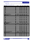
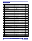
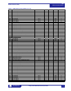
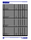
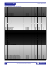
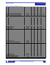
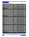
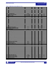
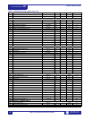
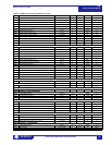
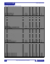
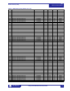
Table 1: 489 Memory Map (Sheet 9 of 29)
ADDR NAME RANGE STEP UNITS FORMAT DEFAULT
1, 2, 3 See Table footnotes on page 39