


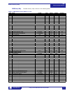
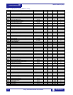
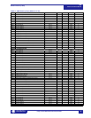


Modbus Memory Map489
Communications Guide
http://www.GEindustrial.com/multilin
10
GE Multilin
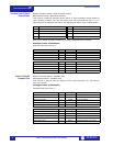
Each communications port can individually select the ID number of the event of
interest by writing address 3003h. This way the front port, rear port and auxiliary
port can read different events from the event recorder simultaneously.
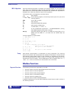
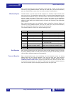
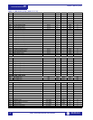
Waveform Capture The 489 stores up to 64 cycles of A/D samples in a waveform capture buffer each
time a trip occurs. The waveform capture buffer is time and date stamped and may
therefore be correlated to a trip in the event record. To access the waveform capture
memory, select the channel of interest by writing the number to the Waveform
Capture Channel Selector (30F5h). Then read the waveform capture data from
address 3100h-31BFh, and read the date, time and line frequency from addresses
30F0h-30F4h.
Each communications port can individually select a Waveform Channel Selector of
interest by writing address 30F5h. This way the front port, rear port and auxiliary
port can read different Waveform Channels simultaneously.
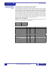
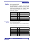
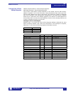
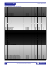
The channel selector must be one of the following values:
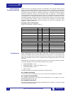
Dual Setpoints Each communications port can individually select an Edit Setpoint Group of interest
by writing address 1342h. This way the front port, rear port and auxiliary port can
read and alter different setpoints simultaneously.
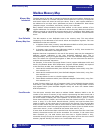
Passcode Operation Each communications port can individually set the Passcode Access by writing
address 88h with the correct Passcode. This way the front port, rear port and
auxiliary port have individual access to the setpoints. Reading address 0203h,
COMMUNICATIONS SETPOINT ACCESS register, provides the user with the current state
of access for the given port. A value of 1 read from this register indicates that the
user has full access rights to changing setpoints from the given port.
VALUE SELECTED A/D SAMPLES SCALE FACTOR
0 Phase A line current 500 counts equals 1 × CT primary
1 Phase B line current 500 counts equals 1 × CT primary
2 Phase C line current 500 counts equals 1 × CT primary
3 Neutral-End phase A current 500 counts equals 1 × CT primary
4 Neutral-End phase B current 500 counts equals 1 × CT primary
5 Neutral-End phase C current 500 counts equals 1 × CT primary
6 Ground current 500 counts equals 1 × CT primary
or 1A for 50:0.025
7 Phase A to neutral voltage 2500 counts equals 120 secondary volts
8 Phase B to neutral voltage 2500 counts equals 120 secondary volts
9 Phase C to neutral voltage 2500 counts equals 120 secondary volts