


Modbus Memory Map489
Communications Guide
http://www.GEindustrial.com/multilin
34
GE Multilin
2A65 Current Demand Alarm Events 0 to 1 1 A F105 0
MONITORING / MW DEMAND
2A70 MW Demand Period 5 to 90 1 min F1 15
2A71 MW Demand Alarm 0 to 2 1 – F115 0
2A72 Assign Alarm Relays (2-5) 1 to 4 1 – F50 16
2A73 MW Demand Limit 10 to 200 1 × Rated F14 125
2A75 MW Demand Alarm Events 0 to 1 1 – F105 0
MONITORING / Mvar DEMAND
2A80 Mvar Demand Period 5 to 90 1 min F1 15
2A81 Mvar Demand Alarm 0 to 2 1 – F115 0
2A82 Assign Alarm Relays (2-5) 1 to 4 1 – F50 16
2A83 Mvar Demand Limit 10 to 200 1 × Rated F14 125
2A85 Mvar Demand Alarm Events 0 to 1 1 – F105 0
MONITORING / MVA DEMAND
2A90 MVA Demand Period 5 to 90 1 min F1 15
2A91 MVA Demand Alarm 0 to 2 1 – F115 0
2A92 Assign Alarm Relays (2-5) 1 to 4 1 – F50 16
2A93 MVA Demand Limit 10 to 200 1 × Rated F14 125
2A95 MVA Demand Alarm Events 0 to 1 1 – F105 0
MONITORING / PULSE OUTPUT
2AB0 Positive kWh Pulse Output Relays (2-5) 1 to 4 1 – F50 0
2AB1 Positive kWh Pulse Output Interval 1 to 50000 1 – F1 10
2AB2 Positive kvarh Pulse Output Relays (2-5) 1 to 4 1 – F50 0
2AB3 Positive kvarh Pulse Output Interval 1 to 50000 1 – F1 10
2AB4 Negative kvarh Pulse Output Relays (2-5) 1 to 4 1 – F50 0
2AB5 Negative kvarh Pulse Output Interval 1 to 50000 1 – F1 10
2AB6 Pulse Width 200 to 1000 1 – F1 200
MONITORING / RUNNING HOUR SETUP
2AC0 Initial Generator Running Hours 0 to 999999 1 h F12 0
2AC2 Generator Running Hour Alarm 0 to 2 1 – F115 0
2AC3 Assign Alarm Relays (2-5) 1 to 4 1 – F50 16
2AC4 Generator Running Hour Limit 1 to 1000000 1 h F12 1000
2AC6 Reserved
ANALOG INPUT/OUTPUT / ANALOG OUTPUT 1
2B00 Analog Output 1 0 to 42 1 – F127 0
ANALOG INPUT/OUTPUT / ANALOG OUTPUT 2
2B01 Analog Output 2 0 to 42 1 – F127 0
ANALOG INPUT/OUTPUT / ANALOG OUTPUT 3
2B02 Analog Output 3 0 to 42 1 – F127 0
ANALOG INPUT/OUTPUT / ANALOG OUTPUT 4
2B03 Analog Output 4 0 to 42 1 – F127 0
ANALOG INPUT/OUTPUT / ANALOG OUTPUTS
2B04 Ia Output Current Minimum 0 to 2000 1 × FLA F3 0
2B05 Ia Output Current Maximum 0 to 2000 1 × FLA F3 125
2B06 Ib Output Current Minimum 0 to 2000 1 × FLA F3 0
2B07 Ib Output Current Maximum 0 to 2000 1 × FLA F3 125
2B08 Ic Output Current Minimum 0 to 2000 1 × FLA F3 0
2B09 Ic Output Current Maximum 0 to 2000 1 × FLA F3 125
2B0A Average Output Current Minimum 0 to 2000 1 × FLA F3 0
2B0B Average Output Current Maximum 0 to 2000 1 × FLA F3 125
2B0C Negative Sequence Current Minimum 0 to 2000 1 %FLA F1 0
2B0D Negative Sequence Current Maximum 0 to 2000 1 %FLA F1 100
2B0E Averaged Generator Load Minimum 0 to 2000 1 × FLA F3 0
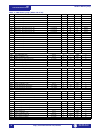
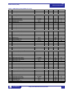
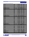
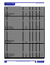
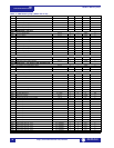
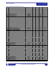
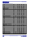
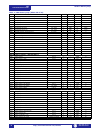
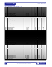
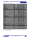
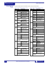
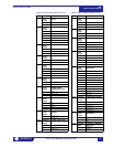
Table 1: 489 Memory Map (Sheet 24 of 29)
ADDR NAME RANGE STEP UNITS FORMAT DEFAULT
1, 2, 3 See Table footnotes on page 39