


Modbus Memory Map489
Communications Guide
http://www.GEindustrial.com/multilin
28
GE Multilin
20A9 Overfrequency Trip Level 1 2501 to 7000 1 Hz F3 6050
20AA Overfrequency Trip Delay 1 1 to 50000 1 s F2 600
20AB Overfrequency Trip Level 2 2501 to 7000 1 Hz F3 6200
20AC Overfrequency Trip Delay 2 1 to 50000 1 s F2 300
VOLTAGE ELEMENTS / NEUTRAL OVERVOLTAGE (FUNDAMENTAL)
20C0 Neutral Overvoltage Alarm 0 to 2 1 – F115 0
20C1 Assign Alarm Relays (2-5) 1 to 4 1 – F50 16
20C2 Neutral Overvoltage Alarm Level 20 to 1000 1 Vsec. F2 30
20C3 Neutral Overvoltage Alarm Delay 1 to 1200 1 s F2 10
20C4 Neutral Overvoltage Alarm Events 0 to 1 1 – F105 0
20C5 Neutral Overvoltage Trip 0 to 2 1 – F115 0
20C6 Assign Trip Relays (1-4) 0 to 3 1 – F50 1
20C7 Neutral Overvoltage Trip Level 20 to 1000 1 V F2 50
20C8 Neutral Overvoltage Trip Delay 1 to 1200 1 s F2 10
20C9 Supervise With Digital Input 0 to 1 1 – F103 0
20CA Neutral Overvoltage Curve Reset Rate 0 to 9999 1 s F2 0
20CB Neutral Overvoltage Trip Element 0 to 1 1 – F208 1
VOLTAGE ELEMENTS / NEUTRAL UNDERVOLTAGE (3rd HARMONIC)
20E0 Low Power Blocking Level 2 to 99 1 × Rated MW F14 5
20E2 Low Voltage Blocking Level 50 to 100 1 × Rated F3 75
20E3 Neutral Undervoltage Alarm 0 to 2 1 – F115 0
20E4 Assign Alarm Relays (2-5) 1 to 4 1 – F50 16
20E5 Neutral Undervoltage Alarm Level 5 to 200 1 V F2 5
20E6 Neutral Undervoltage Alarm Delay 5 to 120 1 s F1 30
20E7 Neutral Undervoltage Alarm Events 0 to 1 1 – F105 0
20E8 Neutral Undervoltage Trip 0 to 2 1 – F115 0
20E9 Assign Trip Relays (1-4) 0 to 3 1 – F50 1
20EA Neutral Undervoltage Trip Level 5 to 200 1 V F2 10
20EB Neutral Undervoltage Trip Delay 5 to 120 1 s F1 30
VOLTAGE ELEMENTS / LOSS OF EXCITATION
2100 Enable Voltage Supervision 0 to 1 1 – F103 0
2101 Voltage Level 70 to 100 1 × rated F3 70
2102 Circle 1 Trip 0 to 2 1 – F115 0
2103 Assign Circle 1 Trip Relays (1-4) 0 to 3 1 – F50 1
2104 Circle 1 Diameter 25 to 3000 1 Ω s F2 250
2105 Circle 1 Offset 10 to 3000 1 Ω sF2 25
2106 Circle 1 Trip Delay 1 to 100 1 s F2 50
2107 Circle 2 Trip 0 to 2 1 – F115 0
2108 Assign Circle 2 Trip Relays (1-4) 0 to 3 1 – F50 1
2109 Circle 2 Diameter 25 to 3000 1 Ω s F2 350
210A Circle 2 Offset 10 to 3000 1 Ω sF2 25
210B Circle 2 Trip Delay 1 to 100 1 s F2 50
VOLTAGE ELEMENTS / DISTANCE ELEMENT
2130 Step Up Transformer Setup 0 to 1 1 – F219 0
2131 Fuse Failure Supervision 0 to 1 1 – F105 0
2132 Zone 1 Trip 0 to 2 1 – F115 0
2133 Assign Zone 1 Trip Relays (1-4) 0 to 3 1 – F50 1
2134 Zone 1 Reach 1 to 5000 1 Ω s F2 100
2135 Zone 1 Angle 50 to 85 1 ° F1 75
2136 Zone 1 Trip Delay 0 to 1500 1 s F2 4
2137 Zone 2 Trip 0 to 2 1 – F115 0
2138 Assign Zone 2 Trip Relays (1-4) 0 to 3 1 – F50 1
2139 Zone 2 Reach 1 to 5000 1 Ω s F2 100
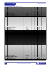
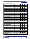
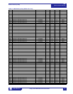
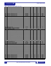
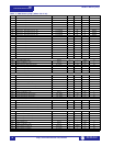
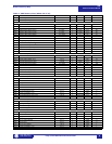
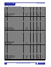
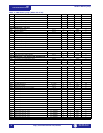
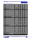
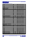
Table 1: 489 Memory Map (Sheet 18 of 29)
ADDR NAME RANGE STEP UNITS FORMAT DEFAULT
1, 2, 3 See Table footnotes on page 39