


Troubleshooting
20 313289S
Troubleshooting
NOTE:
The sprayer operates using air pressure. Many prob-
lems are caused by inadequate air supply. The inlet air
pressure gauge cannot drop below 50 psi (0.35 MPa,
3.5 bar) while running.
NOTE:
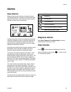
If an error code displays, see Alarms on page 23.
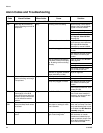
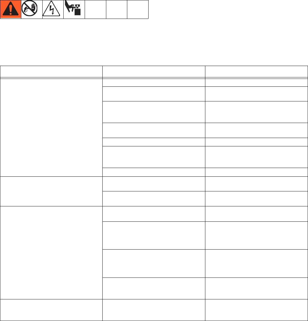
Problem Cause Solution
Display not lit on system with alternator
power supply.
No electric power.
Air valve not turned on. Turn on main air valve to system.
Air supply pressure too low. Increase pressure to 30 psi (0.21 MPa,
2.1 bar) or greater.
Air supply filters plugged. Inlet manifold
filter (604) or air regulator (344) filter
plugged.
Clean filter bowls; replace filter elements.
Page 31.
Turbine air regulator (277) set too low. Adjust to 18 +/- 1 psi (12.6 +/- 10 kPa,
1.26 +/- 0.07 bar).
Alternator turbine failure. Repair or replace turbine. Page 38.
Power supply not connected to main
board.
Check power connections to main board.
See Electrical Schematics, starting on
page 47.
Display board failure. Replace display board. Page 36.
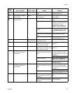
Display not lit on system with alternator
power. Green light is present on FCM
(218) and USB (219), but no green light is
present on back of display module (204).
Faulty CAN cable (268). Or CAN cable is
disconnected.
Check cable and replace. See Alternator
Assembly, page 72.
Faulty display module. Replace display module. See User Inter-
face/Control Box, page 32.
Display not lit on system with wall power
supply. No green light present on back of
display module (204).
No electric power. Disconnect “off” or
breaker “open.”
Reset main disconnect and breaker.
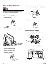
No green lights present on display, FCM,
or USB module.
Check for 24 Vdc on J1, pins 2 and 3, of
power supply. See Electrical Schemat-
ics, starting on page 47. If there is not 24
Vdc, replace with 15V747.
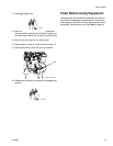
No display power through CAN cable
(266). Green light in present on FCM
(218), but is not present on USB module
(219).
Check CAN cable. Replace if necessary.
See Wall Power Supply Assembly,
page 73.
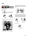
Green light is present on USB module
(219).
Check CAN cable (274). Replace if nec-
essary. See Wall Power Supply Assem-
bly, page 73.
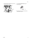
Display not lit on system with wall power
supply. Green light is present on back of
display module (204).
Display module failed. Replace display module. See User Inter-
face/Control Box, page 32.